2N7000
The 2N7000 and BS170 are two different N-channel, enhancement-mode MOSFETs used for low-power switching applications, with different lead arrangements and current ratings. They are sometimes listed together on the same datasheet with other variants 2N7002, VQ1000J, and VQ1000P.[1]
| Type | MOSFET Transistor |
|---|---|
| Working principle | N-channel |
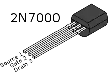
| Pin configuration | G = Gate, D = Drain, S = Source. The symbol doesn't always show the internal diode formed between the substrate and the source/drain/channel. |
| Electronic symbol | |
 | |
The 2N7000 is a widely available and popular part, often recommended as useful and common components to have around for hobbyist use.[2] The BS250P is "a good p-channel analog of the 2N7000."[3]
Packaged in a TO-92 enclosure, both the 2N7000 and BS170 are 60 V devices. The 2N7000 can switch 200 mA. The BS170 can switch 500 mA, with a maximum on-resistance of 5 Ω at 10 V Vgs.
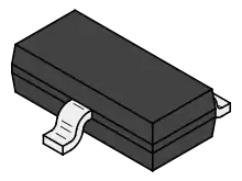
The 2N7002 is another different part with different resistance, current rating and package. The 2N7002 is in a TO-236 package, also known as "small outline transistor" SOT-23 surface-mount, which is the most commonly used three-lead surface-mount package.[4]
Applications
The 2N7000 has been referred to as a "FETlington" and as an "absolutely ideal hacker part."[5] The word "FETlington" is a reference to the Darlington-transistor-like saturation characteristic.
A typical use of these transistors is as a switch for moderate voltages and currents, including as drivers for small lamps, motors, and relays.[1] In switching circuits, these FETs can be used much like bipolar junction transistors, but have some advantages:
- high input impedance of the insulated gate means almost no gate current is required
- consequently no current-limiting resistor is required in the gate input
- MOSFETs, unlike PN junction devices (such as LEDs) can be paralleled because resistance increases with temperature, although the quality of this load balance is largely dependent on the internal chemistry of each individual MOSFET in the circuit
The main disadvantages of these FETs over bipolar transistors in switching are the following:
- susceptibility to cumulative damage from static discharge prior to installation
- circuits with external gate exposure require a protection gate resistor or other static discharge protection
- Non-zero ohmic response when driven to saturation, as compared to a constant junction voltage drop in a bipolar junction transistor
References
- "2N7000/2N7002, VQ1000J/P, BS170" (PDF). Vishay Siliconix datasheet. Retrieved 28 March 2011.
- H. Ward Silver (2005). Two-way radios & scanners for dummies. p. 237. ISBN 0-7645-9582-2.
- Lucio Di Jasio; Tim Wilmshurst; Dogan Ibrahim (2007). PIC microcontrollers. Newnes. p. 520. ISBN 0-7506-8615-4.
- Ray P. Prasad (1997). Surface mount technology: principles and practice (2nd ed.). Springer. p. 112. ISBN 0-412-12921-3.
- Lancaster, Don (February 1986). "Hardware hacker". Modern Electronics. Richard Ross. 3 (2): 115. ISSN 0748-9889.
External links
- Application Notes for Experimenters
- Electric Field Sensor demonstrates extremely high gate impedance with a simple LED circuit
- Driving a single MOSFET Detailed description of usage of a similar MOSFET
- Datasheets
- 2N7002, 300mA, SOT-23 case, NXP Semiconductors
- NX7002AK, 300mA, SOT-23 case, NXP Semiconductors
- 2N7000, 200mA, TO-92 case, On Semiconductor
- BS170, 500mA, TO-92 case, On Semiconductor