Air core gauge
An air core gauge is a specific type of rotary actuator in an analog display gauge that allows an indicator to rotate a full 360 degrees. It is used in gauges and displays, most commonly automotive instrument clusters.

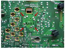
A typical automotive application is shown at the right. The air core gauge is a type of "air-core motor". It may be considered a "gauge movement" or "pointer indication device".[1]
Background
There are four common types of rotary actuators:[2]
- Physical gauges, in which the needle is attached directly to the value being measured; for example, a mechanical pressure gauge
- Analog volt meters or d'Arsonval movements, which consist of a coil and a permanent magnet
- Stepper motors, which move in one-notch increments or steps
- Air-core motors, as described below.
Construction and operation
The air core gauge consists of two independent, perpendicular coils surrounding a hollow chamber. A needle shaft protrudes into the chamber, where a permanent magnet is affixed to the shaft. When current flows through the perpendicular coils, their magnetic fields superimpose and the magnet is free to align with the combined fields.

A typical air core gauge has four terminals, two for each coil, as shown. The two coils are identified as the sine coil and the cosine coil.
Theory
The direction of the overall magnetic field is approximately:
Where and are the coils' sine and cosine currents respectively. The permanent magnet aligns itself with that field, eventually settling near . In this way, by proportioning the current through each coil, the needle can reach all 360° of rotation.[2]
Example
If the sin coil current is 29 mA and the cos current is 50 mA:
The coil current ratio is 0.58, and arctan 0.58 = 30 degrees.
Drivers
Air core gauges require special electronics to properly drive the coils. Some driver integrated circuits have a serial input data port and two pair of output lines. One pair of the output lines drives the sin coil and one pair drives the cos coil.
The input data defines:
- The quadrant to which the actuator will point. This defines the polarity of the voltage to the sin coil and the cos coil.
- The desired number of degrees within the quadrant.
Some typical driver ICs include:
- On Semiconductor CS4172 16 pin dual inline package (DISCONTINUED)
- On Semiconductor CS4192 surface mount package (DISCONTINUED)
- On Semiconductor CS8190 DIP and SOIC surface mount packages
- Melexis MLX10407
- Melexis MLX10420