Charlieplexing
Charlieplexing is a technique for driving a multiplexed display in which relatively few I/O pins on a microcontroller are used e.g. to drive an array of LEDs.
The method uses the tri-state logic capabilities of microcontrollers in order to gain efficiency over traditional multiplexing. Although it is more efficient in its use of I/O, there are issues that cause it to be more complicated to design and render it difficult for larger displays. These issues include duty cycle, current requirements and the forward voltages of the LEDs.

Origin
Charlieplexing was proposed in early 1995 by Charlie Allen at Maxim Integrated[1] following public disclosure to the PICLIST by Graham Daniel (at that time g.daniel.invent.design) of his design using PIC chips to drive rows and columns of bidirectional LEDs. After some discussion on the PICLIST the idea was accepted by the PICLIST community and later was included in a Microchip tricks booklet, but with no attribution. Graham at the time created simple circuits with PIC 12C508 chips driving 12 LEDs off 5 pins with a mini command set to set various lighting displays in motion. As with any multiplexing, there is a requirement to cycle through the in-use LEDs rapidly so that the persistence of the human eye perceives the display to be lit as a whole. Multiplexing can generally be seen by a strobing effect and skewing if the eye's focal point is moved past the display rapidly. The method, however, was known and utilized by various parties much earlier in the 1980s, and has been described in detail as early as in 1979 in a patent by Christopher W. Malinowski, Heinz Rinderle, and Martin Siegle of Department of Research and Development, AEG-Telefunken, Heilbronn, Germany for what they called a "three-state signaling system".[2][3][4]
Traditional multiplexing
| Pins | LEDs |
|---|---|
| 1 | 0 |
| 2 | 2 |
| 3 | 6 |
| 4 | 12 |
| 5 | 20 |
| 6 | 30 |
| 7 | 42 |
| 8 | 56 |
| 9 | 72 |
| 10 | 90 |
| 20 | 380 |
| 40 | 1560 |
| n | n2 − n |
Display multiplexing is very different from multiplexing used in data transmission, although it has the same basic principles. In display multiplexing, the data lines of the displays* are connected in parallel to a common databus on the microcontroller. Then, the displays are turned on and addressed individually. This allows use of fewer I/O pins than it would normally take to drive the same number of displays directly. *Here, each "display" could, for instance, be one calculator digit, not the complete array of digits.
When using Charlieplexing, n drive pins can drive n digits with n − 1 segments. When simplified, it equates to n pins being able to drive n2 − n segments or LEDs. Traditional multiplexing takes many more pins to drive the same number of LEDs; 2n pins must be used to drive n2 LEDs (though a 1-of-n decoder chip can be used to reduce the number of microcontroller I/O pins to ).

If the number of LEDs is known, then the previous equation can be worked backwards to determine the number of pins required. That is, L LEDs can be driven by pins.

Complementary drive
Charlieplexing in its simplest form works by using a diode matrix of complementary pairs of LEDs. The simplest possible Charlieplexed matrix would look like this:


By applying a positive voltage to pin X1 and grounding pin X2, LED1 will light. Since current cannot flow through LEDs in reverse direction at this low voltage, LED2 will remain unlit. If the voltages on pin X1 and pin X2 are reversed, LED2 will light and LED1 will be unlit.
The Charlieplexing technique does not actually make a larger matrix possible when only using two pins, because two LEDs can be driven by two pins without any matrix connections, and without even using tri-state mode. In this two-LED example, Charlieplexing would save one ground wire, which would be needed in a common 2-pin driver situation.
However, the 2-pin circuit serves as a simple example to show the basic concepts before moving on to larger circuits where Charlieplexing actually shows an advantage.
Expanding: tri-state logic
If the circuit above were to be expanded to accommodate 3 pins and 6 LEDs, it would look like this:


This presents a problem, however. In order for this circuit to act like the previous one, one of the pins must be disconnected before applying charge to the remaining two. If, for example, LED5 was intended to be lit, X1 must be charged and X3 must be grounded. However, if X2 is also charged, LED3 would illuminate as well. If X2 was instead grounded, LED1 would illuminate, meaning that LED5 cannot be lit by itself. This can be solved by utilizing the tri-state logic properties of microcontroller pins. Microcontroller pins generally have three states: "high" (5 V), "low" (0 V) and "input". Input mode puts the pin into a high-impedance state, which, electrically speaking, "disconnects" that pin from the circuit, meaning little or no current will flow through it. This allows the circuit to see any number of pins connected at any time, simply by changing the state of the pin. In order to drive the six-LED matrix above, the two pins corresponding to the LED to be lit are connected to 5 V (I/O pin "high" = binary number 1) and 0 V (I/O pin "low" = binary 0), while the third pin is set in its input state.
In doing so, current leakage out of the third pin is prevented, ensuring that the LED wished to be lit is the only one lit. Because the desired LED reduces the voltage available after the resistor, current will not flow across alternate paths (an alternate 2-LED path exists for every pair of pins in the 3-pin diagram, for example), so long as the voltage drop in the desired LED path is less than the total voltage drop across each string of alternative LEDs. However, in the variant with individual resistors this voltage-regulating effect does not affect the alternative paths so you must ensure that all LEDs used will not light with half the supply voltage applied because this variant does not benefit from the voltage-regulating effect of the desired path LED.
By using tri-state logic, the matrix can theoretically be expanded to any size, as long as pins are available. For n pins, n(n − 1) LEDs can be in the matrix. Any LED can be lit by applying 5 V and 0 V to its corresponding pins and setting all of the other pins connected to the matrix to input mode. Under the same constraints as discussed above up to n − 1 LEDs sharing a common positive or negative path can be lit in parallel.
Expanding
The 3-wire circuit can be rearranged to this near-equivalent matrix (resistors have been relocated).

This emphasizes the similarities between ordinary grid multiplex and Charlieplex, and demonstrates the pattern that leads to "the n-squared minus n" rule.
In typical usage on a circuit board the resistors would be physically located at the top of the columns and connected to the input pin. The rows would then be connected directly to the input pin bypassing the resistor.
The first setup is suitable only when identical LEDs are used, whereas in the second configuration with individual resistors, the resistors make it possible to mix different kinds of LEDs by providing each with its appropriate resistor.
In these configurations, the relocated resistors make it possible to light multiple LEDs at the same time row-by-row, instead of requiring that they be lit individually. The row current capacity could be boosted by an NPN emitter follower instead of the typically much weaker I/O pin.
Problems with Charlieplexing
Refresh rate
Because only a single set of LEDs, all having a common anode or cathode, can be lit simultaneously without turning on unintended LEDs, Charlieplexing requires frequent output changes, through a method known as multiplexing. When multiplexing is done, not all LEDs are lit quite simultaneously, but rather one set of LEDs is lit briefly, then another set, and eventually the cycle repeats. If it is done fast enough, they will appear to all be on, all the time, to the human eye because of persistence of vision. In order for a display to not have any noticeable flicker, the refresh rate for each LED must be greater than 50 Hz.
Suppose 8 tri-state pins are used to control 56 LEDs through Charlieplexing, which is enough for 8 7-segment displays (without decimal points). Typically 7-segment displays are made to have a common cathode, sometimes a common anode, but without loss of generality suppose it is a common cathode. All LEDs in all 8 7-segment displays cannot be turned on simultaneously in any desired combination using Charlieplexing. It is impossible to get 56 bits of information directly from 8 trits (the term for a base-3 character, as the pins are 3-state) of information, as 8 trits fundamentally comprises 8 log23, or about 12.7 bits of information, which falls far short of the 56 bits required to turn all 56 LEDs on or off in any arbitrary combination. Instead, the human eye must be fooled by use of multiplexing.
Only one 7-segment display, one set of 7 LEDs can be active at any time. The way this would be done is for the 8 common cathodes of the 8 displays to each get assigned to its own unique pin among the 8 I/O ports. At any time, one and only one of the 8 controlling I/O pins will be actively low, and thus only the 7-segment display with its common cathode connected to that actively low pin can have any of its LEDs on. That is the active 7-segment display. The anodes of the 7 LED segments within the active 7-segment display can then be turned on in any combination by having the other 7 I/O ports either high or in high-impedance mode, in any combination. They are connected to the remaining 7 pins, but through resistors (the common cathode connection is connected to the pin itself, not through a resistor, because otherwise the current through each individual segment would depend on the number of total segments turned on, as they would all have to share a single resistor). But to show a desired number using all 8 digits, only one 7-segment display can be shown at a time, so all 8 must be cycled through separately, and in a 50th of a second for the entire period of 8. Thus the display must be refreshed at 400 Hz for the period-8 cycle through all 8 segments to make the LEDs flash no slower than 50 times per second. This requires constant interruption of whatever additional processing the controller performs, 400 times per second.
Peak current
Due to the decreased duty cycle, the current requirement of a Charlieplexed display increases much faster than it would with a traditionally multiplexed display. As the display gets larger, the average current flowing through the LED must be (roughly) constant in order for it to maintain constant brightness, thus requiring the peak current to increase proportionally. This causes a number of issues that limit the practical size of a Charlieplexed display.
- LEDs often have a maximum peak current rating as well as an average current rating.
- If the microcontroller code crashes, and a one-led-at-a-time Charlieplex is being used, the single LED left lit is under much higher stress than it would be in a row-at-a-time charliplexed display or in a traditionally multiplexed display, increasing the risk of a failure before the fault is spotted.
Requirement for tristate
All the outputs used to drive a Charlieplexed display must be tristate. If the current is low enough to drive the displays directly by the I/O pins of the microcontroller, this is not a problem, but if external tristates must be used, then each tristate will generally require two output lines to control, eliminating most of the advantage of a Charlieplexed display. Since the current from microcontroller pins is typically limited to 20 mA or so, this severely restricts the practical size of a Charlieplexed display. However, it can be done by enabling one segment at a time.[5]
Complexity
Charlieplex matrices are significantly more complicated, both in the required PCB layout and microcontroller programming, than using prebuilt multiplex matrices. This increases design time. Soldering components can also be more time-consuming than for multiplexed LED arrays. A balance between complexity and pin use can be achieved by Charlieplexing several pre-built multiplexed LED arrays together.[6]
Forward voltage
When using LEDs with different forward voltages, such as when using different color LEDs, some LEDs can light when not desired.
In the diagram above it can be seen that if LED 6 has a 4 V forward voltage, and LEDs 1 and 3 have forward voltages of 2 V or less, they will light when LED 6 is intended to, as their current path is shorter. This issue can easily be avoided by comparing forward voltages of the LEDs used in the matrix and checking for compatibility issues. Or, more simply, using LEDs that all have the same forward voltage.[1][7]
This is also a problem where the LEDs are using individual resistors instead of shared resistors, if there is a path through two LEDs that has less LED drop than the supply voltage these LEDs may also illuminate at unintended times.
LED failure
If a single LED fails, by becoming either open-circuit, short-circuit, or leaky (developing a parasitic parallel resistance, which allows current in both directions), the impact will be catastrophic for the display as a whole. Furthermore, the actual problematic LED may be very difficult to identify, because potentially a large set of LEDs which should not be lit may all come on together, and—without detailed knowledge of the circuit—the relation between which LED is bad and what set of LEDs all come on together cannot be easily established.
If the failed LED becomes an open circuit, the voltage between the LED's 2 electrodes may build up until it finds a path through two other LEDs. There are as many such paths as there are pins used to control the array minus 2; if the LED with anode at node m and cathode at node n fails in this way, it may be that every single pair of LEDs in which one's anode is node m, cathode is p for any value of p (with the exceptions that p cannot be m or n, so there are as many possible choices for p as the number of pins controlling the array minus 2), along with the LED whose anode is p and cathode is n, will all light up.
If there are 8 I/O pins controlling the array, this means that there will be 6 parasitic paths through pairs of 2 LEDs, and 12 LEDs may be unintentionally lit, but fortunately this will only happen when the one bad LED is supposed to come on, which may be a small fraction of the time and will exhibit no deleterious symptoms when the problem LED is not supposed to be lit. If the problem is a short between nodes x and y, then every time any LED U with either x or y as its anode or cathode and some node z as its other electrode is supposed to come on (without loss of generality, suppose U's cathode is connected to x), the LED V with cathode y and anode z will light as well, so any time EITHER node x or y is activated as an anode OR a cathode, two LEDs will come on instead of one. In this case, it lights only one additional LED unintentionally, but it does it far more frequently; not merely when the failed LED is supposed to come on, but when any LED that has a pin in common with the failed LED is supposed to come on.
The problematic elements become especially difficult to identify if there are two or more LEDs at fault. What this means is that unlike most methods in which the loss of a single LED merely causes a single burned-out segment, when Charlieplexing is used, one or two burned-out LEDs, whatever the mode of failure, will almost certainly cause a catastrophic cascade of unintended lightings of the LEDs that still work, very likely rendering the entire device completely and immediately unusable. This must be taken into account when considering the required lifetime and failure characteristics of the device being designed.
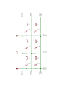
Input data multiplexing
Charlieplexing can also be used to multiplex digital input signals into a microcontroller. The same diode circuits are used, except a switch is placed in series with each diode. To read whether a switch is open or closed, the microcontroller configures one pin as an input with an internal pull-up resistor. The other pin is configured as an output and set to the low logic level. If the input pin reads low, then the switch is closed, and if the input pin reads high, then the switch is open.[8]
One potential application for this is to read a standard (4×3) 12-key numeric keypad using only 4 I/O lines. The traditional row-column scan method requires 4 + 3 = 7 I/O lines. Thus Charlieplexing saves 3 I/O lines; however it adds the expense of 12 diodes, (since the diodes are only free when LEDs are used). A variation of the circuit with only 4 diodes is possible,[8] however this reduces the rollover of the keyboard. The microcontroller can always detect when the data is corrupt, but there is no guarantee it can sense the original key presses, unless only one button is pressed at a time. (However, it is probably possible to arrange the circuit so that if at most any two adjacent buttons are pressed, then no data loss will occur.) The input is only lossless in the 4-diode circuit if only one button is pressed at a time, or if certain problematic multiple key presses are avoided. In the 12-diode circuit, this is not an issue, and there is always a one-to-one correspondence between button presses and input data. However, there are so many diodes that are required to use the method (especially for larger arrays) that there is generally no cost savings over the traditional row-column scan method, unless the cost of a diode is only a fraction of the cost of an I/O pin, where that fraction is one over the number of I/O lines.
Tucoplexing
Micah Elizabeth Scott developed a method to use 3 pins to run 4 LEDs and 4 switches called Tucoplexing.[9]
GuGaplexing
Gugaplexing is like charlieplexing with multiple drive voltages.[10]
Chipiplexing
Chipiplexing adds emitter followers to boost the strength of the row drive allowing rows wider than a single microcontroller port could drive to be lit simultaneously.
Pulse-width modulation
Charlieplexing can even be used to use pulse-width modulation to control the brightness of 12 LEDs with 4 pins.[11]
Code example
In following code example, the circuit[12] uses ATtiny 8-pin microcontroller which has 5 I/O pins to create a 7-segment display. Since a 7-segment display only requires control of 7 individual LEDs, we use 4 of the ATtiny I/O pins as charlieplexed outputs (n*(n-1)). Leaving the fifth I/O pin to be used as digital or analog input or another output.
// ATtiny code
// Reads analog (or digital) input from pin 4 and every time the input goes below a set threshold
// it counts one and displays the increase in count either by activating up one of four LEDs (or transistors)
// or one of twelve charlieplexed LEDs.

// SET THESE VALUES:
int threshold = 500;
int maxCount = 7;
////////////////////
boolean sensorTriggered = false;
int count = 0;
int sensorValue = 0;
long lastDebounceTime = 0;  // the last time the output pin was toggled
long debounceDelay = 50;    // the debounce time; increase if the output flickers
////////////////////////////////////////////////////////////////////////////////
void setup() {
  for (int pin=0; pin<4; pin++) {
    pinMode(pin, OUTPUT);
    digitalWrite(pin, LOW);
  }
  pinMode(4, INPUT);
  digitalWrite(4, HIGH);  // internal pull-up
}
////////////////////////////////////////////////////////////////////////////////
void loop() {
  testDigits();
}
void testDigits() {
  charlieLoop();
}
////////////////////////////////////////////////////////////////////////////////
void readSensor() {
  sensorValue = analogRead(2);  // pin4!
  delay(100);
  if (sensorValue < threshold && sensorTriggered == false) {
    sensorTriggered = true;
    count++;
    if (count > maxCount) count = 0;
    charlieLoop();
  }
  if (sensorValue > threshold) sensorTriggered = false;
}
////////////////////////////////////////////////////////////////////////////////
void charlieLoop() {
  count++;

  for (int i=0; i<1000; i++) {
    for (int c=0; c<count; c++) {
      charliePlexPin(c);
    }
  }
  delay(1000);
  if (count > maxCount) count = 0;
}
////////////////////////////////////////////////////////////////////////////////
void charliePlexPin(int myLed){

  // Make sure we don't feed random voltages to the LEDs
  // during the brief time we are changing pin modes and voltages.
  pinMode(0, INPUT);
  pinMode(1, INPUT);
  pinMode(2, INPUT);
  pinMode(3, INPUT);

  switch(myLed){

  case 0:
    pinMode(0, OUTPUT);
    pinMode(2, OUTPUT);
    digitalWrite(2, LOW);
    digitalWrite(0, HIGH);
    break;

  case 1:
    pinMode(3, OUTPUT);
    pinMode(2, OUTPUT);
    digitalWrite(2, LOW);
    digitalWrite(3, HIGH);
    break;

  case 2:
    pinMode(3, OUTPUT);
    pinMode(1, OUTPUT);
    digitalWrite(1, LOW);
    digitalWrite(3, HIGH);
    break;

  case 3:
    pinMode(1, OUTPUT);
    pinMode(0, OUTPUT);
    digitalWrite(0, LOW);
    digitalWrite(1, HIGH);
    break;

  case 4:
    pinMode(0, OUTPUT);
    pinMode(1, OUTPUT);
    digitalWrite(1, LOW);
    digitalWrite(0, HIGH);
    break;

  case 5:
    pinMode(2, OUTPUT);
    pinMode(0, OUTPUT);
    digitalWrite(0, LOW);
    digitalWrite(2, HIGH);
    break;

  case 6:
    pinMode(2, OUTPUT);
    pinMode(1, OUTPUT);
    digitalWrite(1, LOW);
    digitalWrite(2, HIGH);
    break;
  }
}
////////////////////////////////////////////////////////////////////////////////
void spwm(int freq, int pin, int sp) {
  // call charlieplexing to set correct pin outs:
  //on:
  digitalWrite(pin, HIGH);
  delayMicroseconds(sp * freq);
  // off:
  digitalWrite(pin, LOW);
  delayMicroseconds(sp * (255 - freq));
}
References
- "Charlieplexing - Reduced Pin-Count LED Display Multiplexing". Maxim Integrated. Archived from the original on 7 June 2017. Retrieved 7 June 2017.
Charlie Allen originally championed this technique internally at Maxim, and so the shorthand name "Charlieplexing" came into use to distinguish reduced pin count multiplexing from the traditional method.
- US4319227, Malinowski, Christopher W.; Heinz Rinderle & Martin Siegle, "Three-state signaling system", issued 1982-03-09, assigned to Department of Research and Development, AEG-Telefunken, Heilbronn, Germany
- google.com/patents/US4319227
- patentimages.storage.googleapis.com
- 'Almost no Part Clock' using Charlieplexed 7-segment LED displays.
- Michael E Rule. Charlieplexing with LED dot matrix modules. Accessed March 20, 2013.
- Don Lancaster's Tech Musings #152 is where the name Charlieplexing originated.
- electronicdesign.com, Electronic Design Magazine, 1 page article on Charlieplexing for input data
- "Tucoplexing: A New Charliplex for Buttons and Switches" Article on Hackaday
- "Gugaplex" Article on Makezine
- "Twelve PWM outputs from an ATtiny85" Article on Technoblogy
- "HOW TO GET WHAT YOU WANT". www.kobakant.at. Retrieved 2017-11-13.