Drill bushing
A drill bushing, also known as a jig bushing,[1] is a tool used in metalworking jigs to guide cutting tools, most commonly drill bits. Other tools that are commonly used in a drill bushing include counterbores, countersinks, and reamers. They are designed to guide, position, and support the cutting tool.[2]
In the USA, Customary sized bushings are standardized via ASME B94.33 and metric bushings are standardized via ASME B94.33.1.[3][4] There are over 50,000 standard configurations of customary sized bushings.[2]
Types
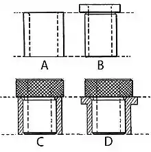
Drill bushings can generally be classified as: press fit bushings or renewable bushings. Other classification methods include by head type, by use, and by liner type (or lack thereof).[2]
Press-fit bushings
Press fit are available in two types with liners or without (wearing bushings). Liner bushings, sometimes called master bushings, are permanently installed into the jig and accept liners that can easily be replaced. Press-fit wearing bushings are used in short run applications or in applications where the tolerance on a hole location is so tight that it cannot facilitate the use of a liner bushing.[3]
Renewable bushings
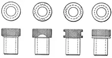
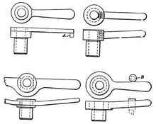
Renewable bushings are installed in liner bushings. This type of bushing is used in large production runs where a bushing will wear out over time or when multiple renewable bushings are used in one liner to provide various sized holes. There are two types of renewable bushings: fixed and slip.[3]
Fixed renewable bushings are used in applications where the liner is meant to be used until it wears out. Slip renewable bushings are designed to be interchangeable with a given sized liner so that two different sized slip renewable bushings can be used in one liner bushing. This facilitates the ability to do multiple machining operations that require different inner diameter (ID) bushings, such as drilling and reaming. They usually have knurled heads so they can be easily removed.[3]
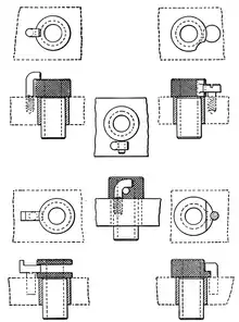
Renewable bushings must be secured in their liner bushing, otherwise the tool can cause it to spin, which rapidly wears out the liner, or chips can force the bushing out of the liner. There are many different types of locking systems for renewable bushings. One system is a dog, which is a collar that is pressed over the head of the bushing and has a long tail. The tail may be bent at the end so it can lock around the edge of the jig plate or it may be left straight if it can butt up against another object. Another option to keep the renewable bushing from rotating is to pin it, either by putting a pin in the renewable bushing and a hole in the liner or vice versa. A more complicated version uses a hole in the bushing collar and a pin with a head; the head on the pin holds the edge of the collar down, but for removal the bushing can be rotated so that the hole lines up with the pin.[5]
Specification
Customary bushings are specified using the following specification layout:[3]
- ID-Type-OD-Length
Where the ID is specified as a decimal, drill letter size, drill number size, or fraction; the OD is an integer that relates to a multiple of a 1⁄64th of an inch (0.40 mm); the length is an integer that relates to a multiple of a 1⁄16th of an inch. The lengths of press-fit bushings are standardized to typical jig plate thicknesses: 5⁄16, 3⁄8, 1⁄2, 3⁄4, 1 , 1 3⁄8, and 1 3⁄4 inch (7.94 mm, 9.53 mm, 12.7 mm, 19.05 mm, 25.4 mm, 34.93 mm and 44.45 mm). The letter "U" is used after the OD number to designate that extra stock should be left on the OD for grinding to size. The type is a letter referring to the following:[3]
- S - Slip renewable
- F - Fixed renewable
- L - Headless liner
- HL - Head liner
- P - Headless press-fit
- H - Head press-fit
The following two tables give the tolerances for the ID and OD.
| Nominal ID [in] | [mm] | _ | Maximum [in] | [mm] | Minimum [in] | [mm] |
|---|---|---|---|---|---|---|
| 0–0.25 in | 0.00–6.35 mm | including | 0.0004 in | 0.01016 mm | 0.0001 in | 0.00254 mm |
| 0.25–0.75 in | 6.35–19.05 mm | incl. | 0.0005 in | 0.0127 mm | 0.0001 in | 0.00254 mm |
| 0.75–1.5 in | 19.05–38.10 mm | incl. | 0.0006 in | 0.01524 mm | 0.0002 in | 0.00508 mm |
| 1.5 in | 38.1 mm | Greater than | 0.0007 in | 0.01778 mm | 0.0003 in | 0.00762 mm |
| Nominal OD [in] | [mm] | _ | Maximum [in] | [mm] | Minimum [in] | [mm] |
|---|---|---|---|---|---|---|
| 5⁄32–1⁄4 in | 3.97–6.35 mm | _ | 0.005 in | 0.127 mm | 0.010 in | 0.254 mm |
| 5⁄16–13⁄64 in | 7.94–5.16 mm | _ | 0.010 in | 0.254 mm | 0.015 in | 0.381 mm |
| 1⁄2 in | 12.7 mm | Greater than | 0.015 in | 0.381 mm | 0.020 in | 0.508 mm |
Custom bushings
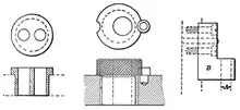
A common problem encountered is when two or more holes are too close for independent standard bushings. In this case one large renewable bushing can be made with two (or more) holes in the proper location (the first example in the image). Another possibility is to make a custom bushing with an eccentric hole and then notches on the outside of the head are used to locate the proper position of the bushing for each location (the middle example in the image). Another common need for a custom bushing is when the hole needed is perpendicular jig plate; in this case a bracket bushing is used. It is a hardened piece of right angle steel that screws to the jig plate and is located with dowel pins.[6]
Design
In general, a drill bushing's length should be at least 2 times the nominal ID.[5]
References
- Colvin & Haas 1922, p. 44.
- Henriksen 1973, p. 154.
- Henriksen 1973, p. 155.
- http://catalog.asme.org/Codes/PrintBook/B94331_1998_Jig_Bushings.cfm%5B%5D
- Henriksen 1973, p. 156.
- Colvin & Haas 1922, pp. 45, 47.
Bibliography
- Colvin, Fred Herbert; Haas, Lucian Levant (1922), Jigs and fixtures (2nd ed.), McGraw-Hill, p. 44.
- Henriksen, Erik Karl (1973), Jig and fixture design manual, Industrial Press Inc., ISBN 978-0-8311-1098-7.