Falsework
Falsework consists of temporary structures used in construction to support a permanent structure until its construction is sufficiently advanced to support itself. For arches, this is specifically called centering. Falsework includes temporary support structures for formwork used to mold concrete[1] in the construction of buildings, bridges, and elevated roadways.
.jpg.webp)
The British Standards of practice for falsework, BS 5975:2008, defines falsework as "Any temporary structure used to support a permanent structure while it is not self-supporting."
History
Falsework has been employed in bridge and viaduct construction since ancient times. The Romans were renowned for its use, as at the Limyra Bridge in Turkey. Until the turn of the 20th century almost all falsework was constructed from timber. To compensate for timber shortages in different regions and to rationalize labor and material usage, new systems were developed.[2]
The major developments include the design of connection devices (coupler), transitions to other spanning beams such as steel pipes or profiles or reusable timber beams, and adjustable steel props. In 1935 W.A. de Vigier designed an adjustable steel prop which revolutionized many aspects of the construction industry including to support slab formwork, wall formwork, trench sheeting and falsework.[3] Materials from which falsework systems are manufactured have also diversified from traditional steel and timber to aluminium components.

In the UK, BS 5975 gives recommendations for the design and use of falsework on construction sites. It was first introduced by the British Standards Institute in March 1982 and the third version was published in 2008 with Amendment 1 in 2011. The new revisions bring the code up to date with methodology developed in the new CDM 2007 regulations and also the requirements of the new European codes EN 12811-1:2003 Temporary works equipment - Part 1: Scaffolds, and EN 12812:2004, Falsework - Performance requirements and general design.
In modern roadway construction
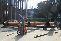 Fabrication
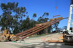 Erection
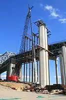 Placement
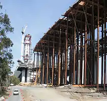 Completed falsework
- Fabrication: Metalworkers fabricate a falsework section from pipe and beams.
- Erection: A section is lifted to a vertical position with the assistance of two forklift operators.
- Placement: The section is guided into position by a ground crew.
- Completed Falsework: Decking and some formwork has been added.
Here we see the use of modern pipe-column falsework, used to support the formwork for a post-tensioned reinforced concrete flyover connector for the eastern span replacement of the San Francisco-Oakland Bay Bridge. When the supports are complete, wood beams and plywood or reusable metal forms will be placed, reinforcing and tenon conduits added, and concrete poured. After curing and any tenon tensioning, wedges will be removed and forms and falsework disassembled.
In bridge construction
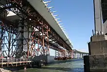
A certain type of bridge, the self-anchored suspension bridge, must be supported during construction, either by the use of cantilever or suspension methods or by support from below. Support from below was used in the construction of the main span of the eastern span replacement of the San Francisco–Oakland Bay Bridge, using parallel prefabricated truss spans.
Cast in place concrete bridges must also be supported during construction. The Sixth Street Viaduct in Los Angeles, California will be cast on falsework and then hung on its network tied arch cables. The release of the falsework will coincide with the tensioning of the arch cables.
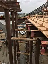
Typical falsework components
Soffit: Plywood sheeting for walking platform and surface to pour bridge against, typically on top of 4x4 lumber at specified spacing of 12".
Camber: Plywood strips that compensate for beam deflection
Stringer: Steel beam that ties caps together
Top Cap: Steel Beam
Post: Steel Pipe or 12x12 lumber.
Bottom Cap: Steel Beam
Wedge Pack: 4x4 lumber cut into wedges for falsework adjustment, various lumber sizes include 2x6s and plywood
Corbel: Distribute load to pads. Typical material is 12x12 lumber and steel beams
Pad: Distribute load to ground. Most commonly 6x16 lumber.
See also
- List of construction methods
- Arch bridge for the use of falsework in bridge construction.
References
| Wikimedia Commons has media related to Falsework. |
- Hardie G.M. (1995) Building Construction: Principles, Practices, and Materials. New Jersey: Prentice Hall. (Pg 116, paragraph 1) ISBN 0133505707
- Burrows B.G (198X) Thesis. (University of Warwick)
- "Archived copy". Archived from the original on 2006-11-28. Retrieved 2008-10-04.CS1 maint: archived copy as title (link)