Flying wing
A flying wing is a tailless fixed-wing aircraft that has no definite fuselage, with its crew, payload, fuel, and equipment housed inside the main wing structure. A flying wing may have various small protuberances such as pods, nacelles, blisters, booms, or vertical stabilizers.[1]
Similar aircraft designs, that are not technically flying wings, are sometimes casually referred to as such. These types include blended wing body aircraft and lifting body aircraft, which have a fuselage and no definite wings. The basic flying wing configuration became an object of significant study during the 1920s, often in conjunction with other tailless designs.
History
Early research

Tailless aircraft have been experimented with since the earliest attempts to fly. Britain's J. W. Dunne was an early pioneer, his swept-wing biplane and monoplane designs displayed inherent stability as early as 1910. His work directly influenced several other designers, including G. T. R. Hill, who developed a series of experimental tailless aircraft designs, collectively known as the Westland-Hill Pterodactyl, during the 1920s and early 1930s.[2] Despite attempts to pursuit orders from the Aviation Ministry, the Pterodactyl programme was ultimately cancelled during the mid 1930s before any order for the Mk. VI was issued.[3]
Germany's Hugo Junkers patented his own wing-only air transport concept in 1910, seeing it as a natural solution to the problem of building an airliner large enough to carry a reasonable passenger load and enough fuel to cross the Atlantic in regular service. He believed that the flying wing's potentially large internal volume and low drag made it an obvious design for this role. His deep-chord monoplane wing was incorporated in the otherwise conventional Junkers J 1 in December 1915. In 1919 he started work on his "Giant" JG1 design, intended to seat passengers within a thick wing, but two years later the Allied Aeronautical Commission of Control ordered the incomplete JG1 destroyed for exceeding postwar size limits on German aircraft. Junkers conceived futuristic flying wings for up to 1,000 passengers; the nearest this came to realization was in the 1931 Junkers G.38 34-seater Grossflugzeug airliner, which featured a large thick-chord wing providing space for fuel, engines, and two passenger cabins. However, it still required a short fuselage to house the crew and additional passengers.
The Soviet Boris Ivanovich Cheranovsky began testing tailless flying wing gliders in 1924. After the 1920s, Soviet designers such as Cheranovsky worked independently and in secret under Stalin.[4] With significant breakthrough in materials and construction methods, aircraft such as the BICh-3,[5] BICh-14, BICh-7A became possible. Men like Chizhevskij and Antonov also came into the spotlight of the Communist Party by designing aircraft like the tailless BOK-5[6] (Chizhevskij) and OKA-33[7] (the first ever built by Antonov) which were designated as "motorized gliders" due to their similarity to popular gliders of the time. The BICh-11, developed by Cheranovsky in 1932,[8] competed with the Horten brothers H1 and Adolf Galland at the Ninth Glider Competitions in 1933, but was not demonstrated in the 1936 summer Olympics in Berlin.
In Germany, Alexander Lippisch worked first on tailless types before progressively moving to flying wings, while the Horten brothers developed a series of flying wing gliders through the 1930s. The H1 glider was flown with partial success in 1933, and the subsequent H2 flown successfully in both glider and powered variants.[9]

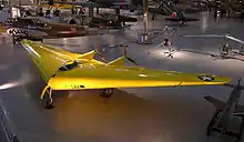
In the United States, from the 1930s Jack Northrop and Cheston L. Eshelman independently worked on their own designs. The Northrop N-1M, a scale prototype for a long-range bomber, first flew in 1940.[10] The Eshelman FW-5, which was commonly referred to as The Wing, was an experimental cabin monoplane.[11] Other 1930s examples of true flying wings include Frenchman Charles Fauvel's AV3 glider of 1933 and the American Freel Flying Wing glider flown in 1937.[12] featuring a self-stabilizing airfoil on a straight wing.
Second World War
During the Second World War, the general understanding of aerodynamic issues became sufficiently understood for work on a range of production-representative prototypes to commence. In Nazi Germany, the Horten brothers were keen proponents of the flying wing configuration, developing their own designs around it. One such aircraft they produced was the Horten H.IV glider, which was produced in low numbers between 1941 and 1943.[13] Several other late-war German military designs were based on the flying wing concept, or variations of it, as a proposed solution to extend the range of otherwise very short-range of aircraft powered by early jet engines.

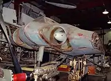
The most famous example of these designs would be the Horten Ho 229 fighter-bomber, which first flew in 1944. It combined a flying wing, or Nurflügel, design with a pair of Junkers Jumo 004 jet engines in its second, or "V2" (V for Versuch) prototype airframe; as such, it was the world's first pure flying wing to be powered by twin jet engines, being first reportedly flown in March 1944. V2 was piloted by Erwin Ziller, who was killed when a flameout in one of its engines led to a crash. Plans were made to produce the type as the Gotha Go 229 during the closing stages of the conflict. Despite intentions to develop the Go 229 and an improved Go P.60 for several roles, including as a night fighter, no Gotha-built Go 229s or P.60s were ever completed.[14] The unflown, nearly completed surviving "V3," or third prototype was captured by American forces and send back for study; it has ended up in storage at the Smithsonian Institution.[15][16]
The Allies also made several relevant advances in the field. During December 1942, Northrop flew the N-9M, a one-third scale development aircraft for a proposed long-range bomber;[17] several were produced, all but one were scrapped following the bomber programme's termination.[18] In Britain, the Baynes Bat glider was flown during wartime; it was a one-third scale experimental aircraft intended to test out the configuration for potential conversion of tanks into temporary gliders.[19]
The British Armstrong Whitworth A.W.52G of 1944 was a glider test bed for tailless research, the company holding ambitions to develop a large flying wing airliner capable of serving transatlantic routes.[20][21] The A.W.52G was later followed up by the Armstrong Whitworth A.W.52, an all-metal jet-powered model capable of high speeds for the era; great attention was paid to laminar flow.[21][22] First flown on 13 November 1947, the A.W.52 yielded disappointing results; the first prototype crashed without loss of life on 30 May 1949, the occasion being the first emergency use of an ejection seat by a British pilot. The second A.W.52 remained flying with the Royal Aircraft Establishment until 1954.[21]
Postwar
Projects continued to examine the flying wing during the postwar era. The work on the Northrop N-1M led to the YB-35 long-range bomber, with pre-production machines flying in 1946. This was superseded the next year by conversion of the type to jet power as the YB-49 of 1947. The design did not offer a great advantage in range, presented a number of technical problems and did not enter production. In the Soviet Union, the BICh-26, became one of the first attempts to produce a supersonic jet flying wing aircraft in 1948;[23] aviation author Bill Gunston referred to the BICh-26 as being ahead of its time.[24] However, the airplane was not accepted by the Soviet military and the design died with Cheranovsky.
Several other nations also opted to undertake flying wing projects. Turkey was one such country, the Turk Hava Kurumu Ucak Fabrikasi producing the THK-13 tailless glider during 1948.[25][26] Multiple British manufacturers also explored the concept at this time. Early proposals for the Avro Vulcan, a nuclear-armed strategic bomber designed by Roy Chadwick, also explored several flying wing arrangements;[27] one such configuration examined for the Vulcan paired the flying wing with a rudimentary forward fuselage and a vertical stabilizer at each wingtip; the delta wing that was actually adopted was arrived at by reducing the wingspan while maintaining the wing area by filling in the space between the wingtips.[28][29]
Following the arrival of supersonic aircraft during the 1950s, military interest in the flying wing was quickly curtailed, as the concept of adopting a thick wing that accommodated the crew and equipment directly conflicted with the optimal thin wing for supersonic flight.
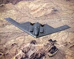
Interest in flying wings was renewed in the 1980s due to their potentially low radar reflection cross-sections. Stealth technology relies on shapes that reflect radar waves only in certain directions, thus making the aircraft hard to detect unless the radar receiver is at a specific position relative to the aircraft—a position that changes continuously as the aircraft moves.[30] This approach eventually led to the Northrop Grumman B-2 Spirit, a flying wing stealth bomber. In this case, the aerodynamic advantages of the flying wing are not the primary reasons for the design's adoption. However, modern computer-controlled fly-by-wire systems allow for many of the aerodynamic drawbacks of the flying wing to be minimized, making for an efficient and effectively stable long-range bomber.[31][32]
Due to the practical need for a deep wing, the flying wing concept is most practical for subsonic aircraft. There has been continual interest in using it in the large transport role where the wing is deep enough to hold cargo or passengers. A number of companies, including Boeing, McDonnell Douglas, and Armstrong Whitworth, have performed considerable design work on flying wing airliners to date,[21] no such airliners have yet entered production as of 2020.
Since the end of the Cold War, numerous unmanned aerial vehicles (UAVs) featuring the flying wing have been produced. Nations have typically used such platforms for aerial reconnaissance; such UAVs include the Lockheed Martin RQ-170 Sentinel,[33][34] the Northrop Grumman Tern,[35][36] and the Nanning Huishi Flying wing. Civilian companies have also experimented with UAVs, such as the Facebook Aquila, as atmospheric satellites.[37][38] Various prototype unmanned combat aerial vehicles (UCAVs) have been produced, including the Dassault nEUROn,[39] the Sukhoi S-70 Okhotnik-B,[40] and the BAE Systems Taranis.[41]
Design
Overview
A clean flying wing is sometimes presented as theoretically the most aerodynamically efficient (lowest drag) design configuration for a fixed wing aircraft. It also would offer high structural efficiency for a given wing depth, leading to light weight and high fuel efficiency.
Because it lacks conventional stabilizing surfaces and the associated control surfaces, in its purest form the flying wing suffers from the inherent disadvantages of being unstable and difficult to control. These compromises are difficult to reconcile, and efforts to do so can reduce or even negate the expected advantages of the flying wing design, such as reductions in weight and drag. Moreover, solutions may produce a final design that is still too unsafe for certain uses, such as commercial aviation.
Further difficulties arise from the problem of fitting the pilot, engines, flight equipment, and payload all within the depth of the wing section. Other known problems with the flying wing design relate to pitch and yaw. Pitch issues are discussed in the article on tailless aircraft. The problems of yaw are discussed below.
Engineering design
A wing that is made deep enough to contain the pilot, engines, fuel, undercarriage and other necessary equipment will have an increased frontal area, when compared with a conventional wing and long-thin fuselage. This can actually result in higher drag and thus lower efficiency than a conventional design. Typically the solution adopted in this case is to keep the wing reasonably thin, and the aircraft is then fitted with an assortment of blisters, pods, nacelles, fins, and so forth to accommodate all the needs of a practical aircraft.
The problem becomes more acute at supersonic speeds, where the drag of a thick wing rises sharply and it is essential for the wing to be made thin. No supersonic flying wing has ever been built.
Directional stability
For any aircraft to fly without constant correction it must have directional stability in yaw.
Flying wings lack anywhere to attach an efficient vertical stabilizer or fin. Any fin must attach directly on to the rear part of the wing, giving a small moment arm from the aerodynamic center, which in turn means that the fin is inefficient and to be effective the fin area must be large. Such a large fin has weight and drag penalties, and can negate the advantages of the flying wing. The problem can be minimized by increasing the wing sweepback and placing twin fins outboard near the tips, as for example in a low-aspect-ratio delta wing, but many flying wings have gentler sweepback and consequently have, at best, marginal stability.
Another solution is to angle or crank the wing tip sections downward with significant anhedral, increasing the area at the rear of the aircraft when viewed from the side.
The frontal area of a swept wing as seen in the direction of the airflow depends on the yaw angle relative to the airflow. Yaw increases the drag of the leading wing and reduces that of the trailing one. With enough sweep-back, differential drag is sufficient to naturally re-align the aircraft. This is the stabilization scheme used in the early Northrop flying wings, in combination with vertical engine nacelles (YB-35) or diminutive stabilizers (YB-49).
A complementary approach uses differential twist or wash out, together with a swept-back wing planform and a suitable airfoil section. Prandtl, Pankonin and others discovered that washout was fundamental to the yaw stability in a turn of the Horten brothers flying wings of the 1930s and 1940s. Due to the necessity for elevons to be located near the wingtips, the one on the upward-moving wing causes drag that impedes turning as it deflects the high-pressure airflow under the wing. The Hortens described a "bell shaped lift distribution" across the span of the wing, with more lift in the center section and less at the tips due to their reduced angle of incidence, or washing out. The restoration of outer lift by the elevon creates a slight thrust for the rear (outer) section of the wing during the turn. When displaced, this vector essentially pulls the trailing wing forward to compensate for the "adverse yaw" caused by the elevon. It did not work well in practice.[42]
Yaw control
In some flying wing designs, any stabilizing fins and associated control rudders would be too far forward to have much effect, thus alternative means for yaw control are sometimes provided.
One solution to the control problem is differential drag: the drag near one wing tip is artificially increased, causing the aircraft to yaw in the direction of that wing. Typical methods include:
- Split ailerons. The top surface moves up while the lower surface moves down. Splitting the aileron on one side induces yaw by creating a differential air brake effect.
- Spoilers. A spoiler surface in the upper wing skin is raised, to disrupt the airflow and increase drag. This effect is generally accompanied by a loss of lift, which must be compensated for either by the pilot or by complex design features.
- Spoilerons. An upper surface spoiler that also acts to reduce lift (equivalent to deflecting an aileron upwards), so causing the aircraft to bank in the direction of the turn—the angle of roll causes the wing lift to act in the direction of turn, reducing the amount of drag required to turn the aircraft's longitudinal axis.
A consequence of the differential drag method is that if the aircraft maneuvers frequently then it will frequently create drag. So flying wings are at their best when cruising in still air: in turbulent air or when changing course, the aircraft may be less efficient than a conventional design.
Bi-directional flying wing

The supersonic bi-directional flying wing design comprises a long-span low speed wing and a short-span high speed wing joined in the form of an unequal cross.
The proposed craft would take off and land with the low-speed wing across the airflow, then rotate a quarter-turn so that the high-speed wing faces the airflow for supersonic travel.[43] NASA has funded a study of the proposal.[44]
The design is claimed to feature low wave drag, high subsonic efficiency and little or no sonic boom.
The proposed low-speed wing would have a thick, rounded airfoil able to contain the payload and a long span for high efficiency, while the high-speed wing would have a thin, sharp-edged airfoil and a shorter span for low drag at supersonic speed.
Related designs
Some related aircraft that are not strictly flying wings have been described as such.
Some types, such as the Northrop Flying Wing (NX-216H), still have a tail stabilizer mounted on tail booms, although they lack a fuselage.
Many hang gliders and microlight aircraft are tailless. Although sometimes referred to as flying wings, these types carry the pilot (and engine where fitted) below the wing structure rather than inside it, and so are not true flying wings.
An aircraft of sharply swept delta planform and deep center section represents a borderline case between flying wing, blended wing body, and/or lifting body configurations.
See also
References
Citations
- Crane, Dale: Dictionary of Aeronautical Terms, third edition, p. 224. Aviation Supplies & Academics, 1997. ISBN 1-56027-287-2.
- Sturtivant (1990), p. 45.
- Mettam (1970).
- "German flying wings". Century-of-flight.net. Retrieved 2012-03-30.
- "History of aircraft construction in the USSR" by V.B. Shavrov, Vol. 1 p. 431 (with images)
- BOK-5, V.A.Chizhevskij
- "History of aircraft construction in the USSR" by V.B. Shavrov, Vol.1 pp. 547–548.
- "Rocket fighter" by William Green, p. 39-41.
- U.S. Naval Technical Mission in Europe. "Technical Report No. 76-45 on. Horten Tailless Aircraft" (PDF). Central Air Documents Office. p. 5. Retrieved 18 July 2010.
Hor ten. H-II Both glider and powered version - (see figures 19 and 20)
- Gunston 1996, p. 26.
- Orbis 1985, p. 1616.
- Pelletier, p. 15.
- Dowling, Stephen. "The Flying Wing Decades Ahead of its Time." BBC News, 2 February 2016.
- "Gotha Go P.60A". www.luft46.com. Retrieved 2 March 2017.
- Maksel, Rebecca (January 11, 2010). "Need to Know - The Luftwaffe's Flying Wing". Air & Space Smithsonian. Smithsonian Institution. Retrieved June 11, 2013.
- "Desperate for victory, the Nazis built an aircraft that was all wing. It didn't work". Smithsonian Insider. 5 April 2018. Retrieved 5 April 2018.
- O'Leary 2007, p. 66.
- O'Leary 2007, p. 68.
- Ellison, Norman (1971). British Gliders and Sailplanes 1922-1970. London: Adam & Charles Black. ISBN 0-7136-1189-8.
- "The A.W. Flying Wing" (pdf). Flight: 464. 9 May 1946. Retrieved 18 July 2010.
- Tapper, O. (1973). Armstrong-Whitworth Aircraft since 1913. London: Putnam. pp. 287–96.
- "Twin-jet A.W.52" (pdf). Flight: 674 following. 19 December 1946. Retrieved 18 July 2010.
- "History of aircraft construction in the USSR" by V.B. Shavrov, Vol. 2. p. 114.
- Gunston, Bill. "The Osprey Encyclopaedia of Russian Aircraft 1875–1995". London, Osprey. 1995.
- Kılıç,M. 2009. Uçan Kanat, THK basımevi, Ankara, p. 5.
- "Turkish Aeronautical Association (THK)", Turkish Aircraft Production (English-language page). (retrieved 15 May 2014)
- Alliott Verdon Roe official web site - Avro Vulcan sketch
- Gunston, W.T. "The Vulcan Story." Flight, 31 January 1958, p. 143.
- Laming 2002, pp. 23, 24.
- "Stealth Aircraft." Archived 21 July 2011 at the Wayback Machine U.S. Centennial of Flight Commission, 2003. Retrieved: 5 November 2012.
- Moir & Seabridge 2008, p. 397
- Sweetman 2005, p. 73
- Fulghum, David A. (8 December 2009). "RQ-170 Has Links to Intelligence Loss to China". Aviation Week & Space Technology. Retrieved 9 December 2009.
- "Mystery UAV operation in Afghanistan". UV Online. 10 April 2009. Archived from the original on 6 December 2009. Retrieved 9 December 2009.
- "Northrop Grumman wins DARPA TERN programme". Flight Global.
- Smith, Rich (23 March 2018). "General Electric and Northrop Grumman Will Put a Drone on Every Boat". The Motley Fool. Retrieved 23 September 2020.
- Hambling, David (9 May 2019). "Solar Drones Are Filling the Skies, But There's Still No Clear Winner". Popular Mechanics. Retrieved 30 May 2019.
- Bellamy III, Woodrow (21 November 2017). "Airbus, Facebook Partner on HAPS Connectivity". Aviation Today. Rockville, MD. Retrieved 5 December 2017.
- Broadbent, Mark (January 2013). "NEUROn Become's Europe's First Stealth Aircraft to Fly". Air International. Vol. 84 no. 1. p. 4. ISSN 0306-5634.
- "Russia's attack drone prototype to start test flights this year". TASS. 8 July 2018. Archived from the original on 18 February 2019. Retrieved 18 February 2019.
- Emery, Daniel (12 July 2010). "MoD lifts lid on unmanned combat plane prototype". BBC News. Archived from the original on 12 July 2010. Retrieved 12 July 2010.
- Guiler, R.W.; Control of a swept wing tailless aircraft through wing morphing, ICAS 2008: 26th Congress of International Council of the Aeronautical Sciences, Paper ICAS 2008-2.7.1, Pages 1–2.
- Zha, Im & Espinal, Toward Zero Sonic-Boom and High Efficiency Supersonic Flight: A Novel Concept of Supersonic Bi-Directional Flying Wing
- Hall, Loura (17 July 2017). "NIAC 2012 Phase I and Phase II Selections". NASA.
Bibliography
- Gunston, Bill (1996). "Beyond the Frontiers: Northrop's Flying Wings". Wings of Fame. London: Aerospace Publishing (Volume 2): 24–37. ISBN 1-874023-69-7. ISSN 1361-2034..
- Kohn, Leo J. (1974). The Flying Wings of Northrop. Milwaukee, WI: Aviation Publications. ISBN 0-87994-031-X.
- Maloney, Edward T. (1975). Northrop Flying Wings. Buena Park, CA: Planes Of Fame Publishers. ISBN 0-915464-00-4.
- O'Leary, Michael (June 2007). "The Shape of Wings to Come". Aeroplane. Vol. 35 no. 6, Issue 410. pp. 65–68.
- The Illustrated Encyclopedia of Aircraft (Part Work 1982-1985). Orbis Publishing.
- Pelletier, Alain J. "Towards the Ideal Aircraft? The Life and Times of the Flying Wing Part One: Beginnings to 1945". Air Enthusiast (64, July–August 1994): 2–17. ISSN 0143-5450..
- Mettam, H.A. (26 March 1970), "The Pterodactyl Story", Flight International, 97 (3185): 514–518
- Moir, Ian; Seabridge, Allan G. (2008), Aircraft Systems: Mechanical, Electrical and Avionics Subsystems Integration, Hoboken, New Jersey: John Wiley & Sons, ISBN 978-0-4700-5996-8.
- Sturtivant, R. (1990). British Research and Development Aircraft. G.T. Foulis. p. 45. ISBN 0854296972..
- Sweetman, Bill (2005), Lockheed Stealth, North Branch, Minnesota: Zenith Imprint, ISBN 978-0-7603-1940-6.
- Laming, Tim (2002). The Vulcan Story: 1952–2002. Enderby, Leicester, UK: Silverdale Books. ISBN 1-85605-701-1..
External links
| Wikimedia Commons has media related to Flying wing aircraft. |
- History of the Flying Wing at Century of Flight.
- The Nurflügel page
- Flight to the Future by Joe Mizrahi, Wings, April 1999, Vol. 29, No. 2
- Glen Edwards and the Flying Wing
- Flying Wings Are Coming, March 1942