Geotechnical centrifuge modeling
Geotechnical centrifuge modeling is a technique for testing physical scale models of geotechnical engineering systems such as natural and man-made slopes and earth retaining structures and building or bridge foundations.[1]

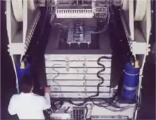
The scale model is typically constructed in the laboratory and then loaded onto the end of the centrifuge, which is typically between 0.2 and 10 metres (0.7 and 32.8 ft) in radius. The purpose of spinning the models on the centrifuge is to increase the g-forces on the model so that stresses in the model are equal to stresses in the prototype. For example, the stress beneath a 0.1-metre-deep (0.3 ft) layer of model soil spun at a centrifugal acceleration of 50 g produces stresses equivalent to those beneath a 5-metre-deep (16 ft) prototype layer of soil in earth's gravity.
The idea to use centrifugal acceleration to simulate increased gravitational acceleration was first proposed by Phillips (1869).[2] Pokrovsky and Fedorov (1936)[3] in the Soviet Union and Bucky (1931) [4] in the United States were the first to implement the idea. Andrew N. Schofield (e.g. Schofield 1980)[5] played a key role in modern development of centrifuge modeling.
Principles of centrifuge modeling
Typical applications

A geotechnical centrifuge is used to test models of geotechnical problems such as the strength, stiffness and capacity of foundations for bridges and buildings, settlement of embankments,[6] stability of slopes, earth retaining structures,[7] tunnel stability and seawalls. Other applications include explosive cratering,[8] contaminant migration in ground water, frost heave and sea ice. The centrifuge may be useful for scale modeling of any large-scale nonlinear problem for which gravity is a primary driving force.
Reason for model testing on the centrifuge
Geotechnical materials such as soil and rock have non-linear mechanical properties that depend on the effective confining stress and stress history. The centrifuge applies an increased "gravitational" acceleration to physical models in order to produce identical self-weight stresses in the model and prototype. The one to one scaling of stress enhances the similarity of geotechnical models and makes it possible to obtain accurate data to help solve complex problems such as earthquake-induced liquefaction, soil-structure interaction and underground transport of pollutants such as dense non-aqueous phase liquids. Centrifuge model testing provides data to improve our understanding of basic mechanisms of deformation and failure and provides benchmarks useful for verification of numerical models.
Scaling laws
Note that in this article, the asterisk on any quantity represents the scale factor for that quantity. For example, in , the subscript m represents "model" and the subscript p represents "prototype" and represents the scale factor for the quantity .[9]
The reason for spinning a model on a centrifuge is to enable small scale models to feel the same effective stresses as a full-scale prototype. This goal can be stated mathematically as
where the asterisk represents the scaling factor for the quantity, is the effective stress in the model and is the effective stress in the prototype.
In soil mechanics the vertical effective stress, for example, is typically calculated by
where is the total stress and is the pore pressure. For a uniform layer with no pore pressure, the total vertical stress at a depth may be calculated by:
where represents the density of the layer and represents gravity. In the conventional form of centrifuge modeling,[9] it is typical that the same materials are used in the model and prototype; therefore the densities are the same in model and prototype, i.e.,
Furthermore, in conventional centrifuge modeling all lengths are scaled by the same factor . To produce the same stress in the model as in the prototype, we thus require , which may be rewritten as
The above scaling law states that if lengths in the model are reduced by some factor, n, then gravitational accelerations must be increased by the same factor, n in order to preserve equal stresses in model and prototype.
Dynamic problems
For dynamic problems where gravity and accelerations are important, all accelerations must scale as gravity is scaled, i.e.
Since acceleration has units of , it is required that
Hence it is required that :, or
Frequency has units of inverse of time, velocity has units of length per time, so for dynamic problems we also obtain
Diffusion problems
For model tests involving both dynamics and diffusion, the conflict in time scale factors may be resolved by scaling the permeability of the soil [9]
Scaling of other quantitites
(this section obviously needs work!)
scale factors for energy, force, pressure, acceleration, velocity, etc. Note that stress has units of pressure, or force per unit area. Thus we can show that
Substituting F = m∙a (Newton's law, force = mass ∙ acceleration) and r = m/L3 (from the definition of mass density).
Scale factors for many other quantities can be derived from the above relationships. The table below summarizes common scale factors for centrifuge testing.
Scale Factors for Centrifuge Model Tests (from Garnier et al., 2007 [9]) (Table is suggested to be added here)
Value of centrifuge in geotechnical earthquake engineering


Large earthquakes are infrequent and unrepeatable but they can be devastating. All of these factors make it difficult to obtain the required data to study their effects by post earthquake field investigations. Instrumentation of full scale structures is expensive to maintain over the large periods of time that may elapse between major temblors, and the instrumentation may not be placed in the most scientifically useful locations. Even if engineers are lucky enough to obtain timely recordings of data from real failures, there is no guarantee that the instrumentation is providing repeatable data. In addition, scientifically educational failures from real earthquakes come at the expense of the safety of the public. Understandably, after a real earthquake, most of the interesting data is rapidly cleared away before engineers have an opportunity to adequately study the failure modes.
Centrifuge modeling is a valuable tool for studying the effects of ground shaking on critical structures without risking the safety of the public. The efficacy of alternative designs or seismic retrofitting techniques can compared in a repeatable scientific series of tests.
Verification of numerical models
Centrifuge tests can also be used to obtain experimental data to verify a design procedure or a computer model. The rapid development of computational power over recent decades has revolutionized engineering analysis. Many computer models have been developed to predict the behavior of geotechnical structures during earthquakes and other loads. Before a computer model can be used with confidence, it must be proven to be valid based on evidence. The meager and unrepeatable data provided by natural earthquakes, for example, is usually insufficient for this purpose. Verification of the validity of assumptions made by a computational algorithm is especially important in the area of geotechnical engineering due to the complexity of soil behavior. Soils exhibit highly non-linear behavior, their strength and stiffness depend on their stress history and on the water pressure in the pore fluid, all of which may evolve during the loading caused by an earthquake. The computer models which are intended to simulate these phenomena are very complex and require extensive verification. Experimental data from centrifuge tests is useful for verifying assumptions made by a computational algorithm. If the results show the computer model to be inaccurate, the centrifuge test data provides insight into the physical processes which in turn stimulates the development of better computer models.
See also
References
- Craig, W.H. (2001). "The seven ages of centrifuge modelling". Proc. Workshop on constitutive and centrifuge modeling: two extremes. pp. 165–174.
- Phillips, Edouard (1869), De l’equilibre des solides elastiques semblables, 68, C. R. Acad. Sci., Paris, pp. 75–79
- Pokrovsky, G. Y.; Fedorov, I. S. (1936), Studies of soil pressures and soil deformations by means of a centrifuge, 1, Proc. 1st Int. Conf. On Soil Mechanics & Foundation Engineering
- Bucky, P.B. (1931), The use of models for the study of mining problems, Technical Publication 425, New York: Am. Inst. Of Min. & Met. Engng.
- Schofield, A. N. (1980), Cambridge geotechnical centrifuge operations, 30, Géotechnique, pp. 227–268
- Malushitsky (1975), The centrifugal modelling of waste-heap embankments, Russian edition, Kiev, English translation edited by A. N. Schofield, Cambridge University Press (1981)
- Mikasa, M.; Takada, N.; Yamada, K. (1969). "Centrifugal model test of a rockfill dam.". Proc. 7th Int. Conf. Soil Mechanics & Foundation Engineering 2:. México: Sociedad Mexicana de Mecánica de Suelos. pp. 325–333.
- Schmidt RM (1988). "Centrifuge contributions to cratering technology". In Craig, et al. (eds.). Centrifuges in Soil Mechanics. Balkema. pp. 199–202.
- Garnier, J.; Gaudin, C.; Springman, S.M.; Culligan, P.J.; Goodings, D.J.; Konig, D.; Kutter, B.L.; Phillips, R.; Randolph, M.F.; Thorel, L. (2007), "Catalogue of scaling laws and similitude questions in geotechnical centrifuge modelling", International Journal of Physical Modelling in Geotechnics, 7 (3): 1–23
- Schofield (1993), From cam clay to centrifuge models, JSSMFE Vol. 41, No. 5 Ser. No. 424 pp 83– 87, No. 6 Ser. No. 425 pp 84–90, No. 7, Ser. No. 426 pp 71–78.