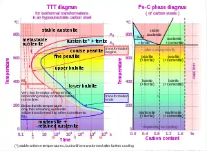
Isothermal transformation diagram
These are mainly usefull for one material how to composition given.

Isothermal transformation diagrams (also known as time-temperature-transformation (TTT) diagrams) are plots of temperature versus time (usually on a logarithmic scale). They are generated from percentage transformation-vs time measurements, and are useful for understanding the transformations of an alloy steel at elevated temperatures.
An isothermal transformation diagram is only valid for one specific composition of material, and only if the temperature is held constant during the transformation, and strictly with rapid cooling to that temperature. Though usually used to represent transformation kinetics for steels, they also can be used to describe the kinetics of crystallization in ceramic or other materials. Time-temperature-precipitation diagrams and time-temperature-embrittlement diagrams have also been used to represent kinetic changes in steels.
Isothermal transformation (IT) diagram or the C-curve is associated with mechanical properties, microconstituents/microstructures, and heat treatments in carbon steels. Diffusional transformations like austenite transforming to a cementite and ferrite mixture can be explained using the sigmoidal curve; for example the beginning of pearlitic transformation is represented by the pearlite start (Ps) curve. This transformation is complete at Pf curve. Nucleation requires an incubation time. The rate of nucleation increases and the rate of microconstituent growth decreases as the temperature decreases from the liquidus temperature reaching a maximum at the bay or nose of the curve. Thereafter, the decrease in diffusion rate due to low temperature offsets the effect of increased driving force due to greater difference in free energy. As a result of the transformation, the microconstituents, pearlite and bainite, form; pearlite forms at higher temperatures and bainite at lower.

Austenite is slightly undercooled when quenched below Eutectoid temperature. When given more time, stable microconstituents can form: ferrite and cementite. Coarse pearlite is produced when atoms diffuse rapidly after phases that form pearlite nucleate. This transformation is complete at the pearlite finish time (Pf).
However, greater undercooling by rapid quenching results in formation of martensite or bainite instead of pearlite. This is possible provided the cooling rate is such that the cooling curve intersects the martensite start temperature or the bainite start curve before intersecting the Ps curve. The martensite transformation being a diffusionless shear transformation is represented by a straight line to signify the martensite start temperature.
References
- Materials science and Engineering, an introduction. William D. Callister Jr, 7th Ed, Wiley and sons publishing. Pages 258, 326, 462
- The Science and Engineering of Materials. Donald R. Askeland, Pradeep P. Fulay, Wendelin J. Wright, 6th Ed, Cengage Learning. Pages 470-5.