Light meter
A light meter is a device used to measure the amount of light. In photography, a light meter (more correctly an exposure meter) is used to determine the proper exposure for a photograph. The meter will include either a digital or analog calculator which displays the correct shutter speed and f-number for optimum exposure, given a certain lighting situation and film speed. Similarly, exposure meters are also used in the fields of cinematography and scenic design, in order to determine the optimum light level for a scene.
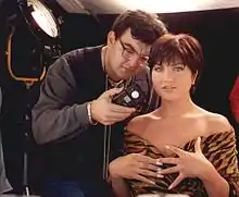
Light meters are used in the general field of architectural lighting design to verify proper installation and performance of a building lighting system, and in assessing the light levels for growing plants.
Use in photography
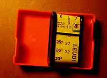
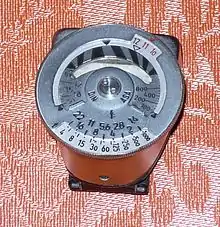
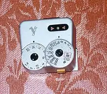
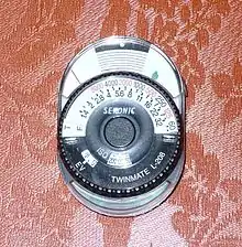
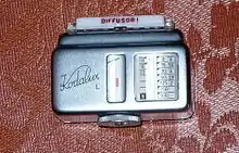

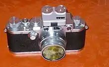
The earliest type of light meters were called extinction meters and contained a numbered or lettered row of neutral density filters of increasing density. The photographer would position the meter in front of his subject and note the filter with the greatest density that still allowed incident light to pass through. The letter or number corresponding to the filter was used as an index into a chart of appropriate aperture and shutter speed combinations for a given film speed.
Extinction meters suffered from the problem that they depended on the light sensitivity of the human eye (which can vary from person to person) and subjective interpretation.
Later meters removed the human element and relied on technologies incorporating selenium, CdS, and silicon photodetectors.
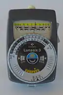
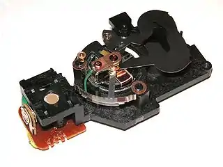
Selenium and silicon light meters use sensors that are photovoltaic: they generate a voltage proportional to light exposure. Selenium sensors generate enough voltage for direct connection to a meter; they need no battery to operate and this made them very convenient in completely mechanical cameras. Selenium sensors however cannot measure low light accurately (ordinary lightbulbs can take them close to their limits) and are altogether unable to measure very low light, such as candlelight, moonlight, starlight etc. Silicon sensors need an amplification circuit and require a power source such as batteries to operate. CdS light meters use a photoresistor sensor whose electrical resistance changes proportionately to light exposure. These also require a battery to operate. Most modern light meters use silicon or CdS sensors. They indicate the exposure either with a needle galvanometer or on an LCD screen.
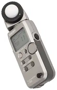
Many modern consumer still and video cameras include a built-in meter that measures a scene-wide light level and are able to make an approximate measure of appropriate exposure based on that. Photographers working with controlled lighting and cinematographers use handheld light meters to precisely measure the light falling on various parts of their subjects and use suitable lighting to produce the desired exposure levels.
There are two general types of light meters: reflected-light and incident-light. Reflected-light meters measure the light reflected by the scene to be photographed. All in-camera meters are reflected-light meters. Reflected-light meters are calibrated to show the appropriate exposure for “average” scenes. An unusual scene with a preponderance of light colors or specular highlights would have a higher reflectance; a reflected-light meter taking a reading would incorrectly compensate for the difference in reflectance and lead to underexposure. Badly underexposed sunset photos are common exactly because of this effect: the brightness of the setting sun fools the camera's light meter and, unless the in-camera logic or the photographer take care to compensate, the picture will be grossly underexposed and dull.
This pitfall (but not in the setting-sun case) is avoided by incident-light meters which measure the amount of light falling on the subject using an integrating sphere (usually, a translucent hemispherical plastic dome is used to approximate this) placed on top of the light sensor. Because the incident-light reading is independent of the subject's reflectance, it is less likely to lead to incorrect exposures for subjects with unusual average reflectance. Taking an incident-light reading requires placing the meter at the subject's position and pointing it in the general direction of the camera, something not always achievable in practice, e.g., in landscape photography where the subject distance approaches infinity.
Another way to avoid under- or over-exposure for subjects with unusual reflectance is to use a spot meter: a reflected-light meter that measures light in a very tight cone, typically with a one degree circular angle of view. An experienced photographer can take multiple readings over the shadows, midrange and highlights of the scene to determine optimal exposure, using systems like the Zone System.
Many modern cameras include sophisticated multi-segment metering systems that measure the luminance of different parts of the scene to determine the optimal exposure. When using a film whose spectral sensitivity is not a good match to that of the light meter, for example orthochromatic black-and-white or infrared film, the meter may require special filters and re-calibration to match the sensitivity of the film.
There are other types of specialized photographic light meters. Flash meters are used in flash photography to verify correct exposure. Color meters are used where high fidelity in color reproduction is required. Densitometers are used in photographic reproduction.
Exposure meter calibration
In most cases, an incident-light meter will cause a medium tone to be recorded as a medium tone, and a reflected-light meter will cause whatever is metered to be recorded as a medium tone. What constitutes a “medium tone” depends on meter calibration and several other factors, including film processing or digital image conversion.
Meter calibration establishes the relationship between subject lighting and recommended camera settings. The calibration of photographic light meters is covered by ISO 2720:1974.
Exposure equations
For reflected-light meters, camera settings are related to ISO speed and subject luminance by the reflected-light exposure equation:
where
- is the relative aperture (f-number)
- is the exposure time ("shutter speed") in seconds
- is the average scene luminance
- is the ISO arithmetic speed
- is the reflected-light meter calibration constant
For incident-light meters, camera settings are related to ISO speed and subject illuminance by the incident-light exposure equation:
where
- is the illuminance
- is the incident-light meter calibration constant
Calibration constants
Determination of calibration constants has been largely subjective; ISO 2720:1974 states that
The constants and shall be chosen by statistical analysis of the results of a large number of tests carried out to determine the acceptability to a large number of observers, of a number of photographs, for which the exposure was known, obtained under various conditions of subject manner and over a range of luminances.
In practice, the variation of the calibration constants among manufacturers is considerably less than this statement might imply, and values have changed little since the early 1970s.
ISO 2720:1974 recommends a range for of 10.6 to 13.4 with luminance in cd/m². Two values for are in common use: 12.5 (Canon, Nikon, and Sekonic[1]) and 14 (Minolta,[2] Kenko,[2] and Pentax); the difference between the two values is approximately 1/6 EV.
The earliest calibration standards were developed for use with wide-angle averaging reflected-light meters (Jones and Condit 1941). Although wide-angle average metering has largely given way to other metering sensitivity patterns (e.g., spot, center-weighted, and multi-segment), the values for determined for wide-angle averaging meters have remained.
The incident-light calibration constant depends on the type of light receptor. Two receptor types are common: flat (cosine-responding) and hemispherical (cardioid-responding). With a flat receptor, ISO 2720:1974 recommends a range for of 240 to 400 with illuminance in lux; a value of 250 is commonly used. A flat receptor typically is used for measurement of lighting ratios, for measurement of illuminance, and occasionally, for determining exposure for a flat subject.
For determining practical photographic exposure, a hemispherical receptor has proven more effective. Don Norwood, inventor of incident-light exposure meter with a hemispherical receptor, thought that a sphere was a reasonable representation of a photographic subject. According to his patent (Norwood 1938), the objective was
to provide an exposure meter which is substantially uniformly responsive to light incident upon the photographic subject from practically all directions which would result in the reflection of light to the camera or other photographic register.
and the meter provided for "measurement of the effective illumination obtaining at the position of the subject."
With a hemispherical receptor, ISO 2720:1974 recommends a range for of 320 to 540 with illuminance in lux; in practice, values typically are between 320 (Minolta) and 340 (Sekonic). The relative responses of flat and hemispherical receptors depend upon the number and type of light sources; when each receptor is pointed at a small light source, a hemispherical receptor with = 330 will indicate an exposure approximately 0.40 step greater than that indicated by a flat receptor with = 250. With a slightly revised definition of illuminance, measurements with a hemispherical receptor indicate “effective scene illuminance.”
Calibrated reflectance
It is commonly stated that reflected-light meters are calibrated to an 18% reflectance,[3] but the calibration has nothing to do with reflectance, as should be evident from the exposure formulas. However, some notion of reflectance is implied by a comparison of incident- and reflected-light meter calibration.
Combining the reflected-light and incident-light exposure equations and rearranging gives
Reflectance is defined as
A uniform perfect diffuser (one following Lambert's cosine law) of luminance emits a flux density of ; reflectance then is
Illuminance is measured with a flat receptor. It is straightforward to compare an incident-light measurement using a flat receptor with a reflected-light measurement of a uniformly illuminated flat surface of constant reflectance. Using values of 12.5 for and 250 for gives
With a of 14, the reflectance would be 17.6%, close to that of a standard 18% neutral test card. In theory, an incident-light measurement should agree with a reflected-light measurement of a test card of suitable reflectance that is perpendicular to the direction to the meter. However, a test card seldom is a uniform diffuser, so incident- and reflected-light measurements might differ slightly.
In a typical scene, many elements are not flat and are at various orientations to the camera, so that for practical photography, a hemispherical receptor usually has proven more effective for determining exposure. Using values of 12.5 for and 330 for gives
With a slightly revised definition of reflectance, this result can be taken as indicating that the average scene reflectance is approximately 12%. A typical scene includes shaded areas as well as areas that receive direct illumination, and a wide-angle averaging reflected-light meter responds to these differences in illumination as well as differing reflectances of various scene elements. Average scene reflectance then would be
where “effective scene illuminance” is that measured by a meter with a hemispherical receptor.
ISO 2720:1974 calls for reflected-light calibration to be measured by aiming the receptor at a transilluminated diffuse surface, and for incident-light calibration to be measured by aiming the receptor at a point source in a darkened room. For a perfectly diffusing test card and perfectly diffusing flat receptor, the comparison between a reflected-light measurement and an incident-light measurement is valid for any position of the light source. However, the response of a hemispherical receptor to an off-axis light source is approximately that of a cardioid rather than a cosine, so the 12% “reflectance” determined for an incident-light meter with a hemispherical receptor is valid only when the light source is on the receptor axis.
Cameras with internal meters
Calibration of cameras with internal meters is covered by ISO 2721:1982; nonetheless, many manufacturers specify (though seldom state) exposure calibration in terms of , and many calibration instruments (e.g., Kyoritsu-Arrowin multi-function camera testers[4] ) use the specified to set the test parameters.
Exposure determination with a neutral test card
If a scene differs considerably from a statistically average scene, a wide-angle averaging reflected-light measurement may not indicate the correct exposure. To simulate an average scene, a substitute measurement sometimes is made of a neutral test card, or gray card.
At best, a flat card is an approximation to a three-dimensional scene, and measurement of a test card may lead to underexposure unless adjustment is made. The instructions for a Kodak neutral test card recommend that the indicated exposure be increased by ½ step for a frontlighted scene in sunlight. The instructions also recommend that the test card be held vertically and faced in a direction midway between the Sun and the camera; similar directions are also given in the Kodak Professional Photoguide. The combination of exposure increase and the card orientation gives recommended exposures that are reasonably close to those given by an incident-light meter with a hemispherical receptor when metering with an off-axis light source.
In practice, additional complications may arise. Many neutral test cards are far from perfectly diffuse reflectors, and specular reflections can cause increased reflected-light meter readings that, if followed, would result in underexposure. It is possible that the neutral test card instructions include a correction for specular reflections.
Use in illumination
Light meters or light detectors are also used in illumination. Their purpose is to measure the illumination level in the interior and to switch off or reduce the output level of luminaires. This can greatly reduce the energy burden of the building by significantly increasing the efficiency of its lighting system. It is therefore recommended to use light meters in lighting systems, especially in rooms where one cannot expect users to pay attention to manually switching off the lights. Examples include hallways, stairs, and big halls.
There are, however, significant obstacles to overcome in order to achieve a successful implementation of light meters in lighting systems, of which user acceptance is by far the most formidable. Unexpected or too frequent switching and too bright or too dark rooms are very annoying and disturbing for users of the rooms. Therefore, different switching algorithms have been developed:
- difference algorithm, where lights are switched on at a lower light level than they switch off, thus taking ensuring the difference between the light level of the 'on' state and 'off' state is not too big
- time delay algorithms:
- a certain amount of time must pass since the last switch
- a certain amount of time at a sufficient illumination level must pass.
Other uses
In Scientific Research & Development uses, a light meter consists of a radiometer (the electronics/readout), a photo-diode or sensor (generates an output when exposed to electromagnetic radiation/light) a filter (used to modify the incoming light so only the desired portion of incoming radiation reaches the sensor) and a cosine correcting input optic (assures the sensor can see the light coming in from all directions accurately).
When the word light meter or photometer is used in place of radiometer or optometer, or it is often assumed the system was configured to see only visible light. Visible light sensors are often called illuminance or photometric sensors because they have been filtered to be sensitive only to 400-700 nanometers (nm) mimicking the human eyes sensitivity to light. How accurately the meter measures often depends on how well the filtration matches the human eyes response.
The sensor will send a signal to the meter that is proportional to the amount of light that reaches the sensor after being collected by the optics and passing through the filter. The meter then converts the incoming signal (typically current or voltage) from the sensor into a reading of calibrated units such as Foot-Candles (fc) or Lux (lm/m^2). Calibration in fc or lux, is the second most important feature of a light meter. It not only converts the signal from V or mA, but it also provides accuracy and unit to unit repeatability. National Institute of Standards and Technology (NIST) traceability and ISO/IEC 17025 accreditation are two well known terms that verify the system includes a valid calibration.
The meter/radiometer/photometer portion may have many features including:
Zero: subtracts ambient/back ground light levels, or stabilize the meter to the working environment
Hold: freezes the value on the display.
Range: for systems that are not linear and auto ranging this function allows the user to select the portion of the meter electronics that best handles the signal level in use.
Units: For illuminance the units are typically only lux and foot-candles but many light meters can also be used for UV, VIS and IR applications so the readout could change to W/cm^2, candela, Watts etc.
Integrate: sums up the values into a dose or exposure level i.e. lux*sec or J/cm^2.
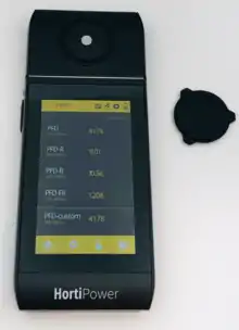
Along with having a variety of features, a light meter may also be usable for a variety of applications. These may include the measurement of other bands of light such UVA, UVB, UVC and Near IR. For example, UVA and UVB light meters are used for phototherapy or treatment of skin conditions, germicidal radiometers are used for measuring the UVC level from lamps used for disinfection and sterilization, luminance meters are used to measure the brightness of a sign, display or exit sign, PAR quantum sensors are used to measure how much of a given light source's emission will help plants grow, and UV-curing radiometers test how much of the lights emission is effective for hardening a glue, plastic, or protective coating.
Some light meters also have the ability to provide a readout in many different units. Lux and footcandles are the common units for visible light, but so are Candelas, Lumens, and Candela per square meter. In the realm of disinfection, UVC is typically measured in watts per square centimeter, or watts for a given individual lamp assembly, whereas systems used in the context of the curing of coatings often provide readouts in Joules per Square centimeter. Regular measurements of UVC light intensity thus can serve to provide assurance of proper disinfection of water and food-preparation surfaces, or reliable coating hardness in painted products.
Although a light meter can take the form of a very simple handheld tool with one-button operation, there are also many advanced light-measurement systems available for use in numerous different applications. These can be incorporated into automated systems that can, for example, wipe lamps clean when a certain reduction in output is detected, or that can trigger an alarm when lamp-failure occurs.
See also
| Wikimedia Commons has media related to Light meters. |
- Selenium meter
- Photometer | Photodetector
- Colorimetry | Photometry | Radiometry
- Light value
- Photomultiplier tubes for detecting light at very low levels.
- PIN diode solid state electronic devices for detecting incident light.
Notes
- Specifications for Sekonic light meters are available on the Sekonic web site under “Products.”
- Konica Minolta Photo Imaging, Inc. left the camera business on March 31, 2006. Rights and tooling for Minolta exposure meters were acquired by Kenko Co, Ltd. in 2007. Specifications for the Kenko meters are essentially the same as for the equivalent Minolta meters.
- Some authors (Ctein 1997, 29) have argued that the calibrated reflectance is closer to 12% than to 18%.
- Specifications for Kyoritsu testers are available on the C.R.I.S. Camera Services web site under “kyoritsu test equipment.”
References
- Ctein. 1997. Post Exposure: Advanced Techniques for the Photographic Printer. Boston: Focal Press. ISBN 0-240-80299-3.
- Eastman Kodak Company. Instructions for Kodak Neutral Test Card, 453-1-78-ABX. Rochester: Eastman Kodak Company.
- Eastman Kodak Company. 1992. Kodak Professional Photoguide. Kodak publication no. R-28. Rochester: Eastman Kodak Company.
- ISO 2720:1974. General Purpose Photographic Exposure Meters (Photoelectric Type) — Guide to Product Specification. International Organization for Standardization.
- ISO 2721:2013. Photography — Film-based cameras — Automatic controls of exposure. International Organization for Standardization.
- Jones, Loyd A., and H. R. Condit. 1941. The Brightness Scale of Exterior Scenes and the Correct Computation of Photographic Exposure. Journal of the Optical Society of America. 31:651–678.
- Norwood, Donald W. 1938. Exposure Meter. US Patent 2,214,283, filed 14 November 1938, and issued 10 September 1940.
External links
- The Problem with Lux Meters An article suggesting that Lux meter may read incorrectly when measuring light not from a tungsten source (i.e. fluorescent, metal halide, sodium, LED and other types).
- Exposure Metering: Relating Subject Lighting to Film Exposure (PDF) A discussion of meter calibration and its practical effects.
- Estimating Luminance and Illuminance (PDF) A Kodak guide to using a camera's exposure meter.
- Basic Light Measurement Principles An article from International Light Technologies on basic principles