List of WWII Maybach engines
This is an incomplete list of gasoline engines designed by Maybach AG, manufactured by Maybach and other firms under licence, and fitted in various German tanks and half-tracks before and during World War II. Until the mid 1930s, German military vehicle manufacturers could source their power plants from a variety of engine makers; by October 1935 the design and manufacture of almost all tank and half-track engines was concentrated in one company, Maybach AG, located in Friedrichshafen on Lake Constance.[1]
.jpg.webp)
The firm designed and made a wide range of 4, 6, and 12-cylinder engines from 2.5 to 23 litres; these powered the basic chassis designs for approximately ten tank types (including tank hunters and assault guns), six half-track artillery tractor designs, plus two series of derived armoured personnel carriers. Maybach also designed a number of gearboxes fitted to these vehicles, made under licence by other manufacturers. Friedrichshafen was also home to the Zahnradfabrik (ZF) factory which made gearboxes for Panzer III, IV, Panther and Tiger tanks. Both Maybach and ZF (and Dornier) were originally subsidiaries of Luftschiffbau Zeppelin GmbH, which also had a factory in the town.
Maybach used various combinations of factory letter codes (discussed below) which specified the particular ancillaries to be supplied with each engine variant: the same basic model could be fitted in a number of vehicles, according to the original manufacturer's design requirements. For example, the basic 3.8 and 4.2 litre straight-6 engines (the NL38 and HL42) fitted in various half-tracks could be supplied in at least 9 different configurations, although every single component was to be found in a single unified parts list.[2]
However, as the war progressed, a number of problems hampered the German armaments production effort. The factory's inability to manufacture enough complete engines as well as a huge range of spare parts, meant that there was often a lack of both. Conflicts between the civilian Reich Ministry of Armaments and Munitions and the German Army led to a failure to set up an adequate distribution system, and consequent severe shortages of serviceable combat vehicles. In April 1944 an Allied bombing raid put the Maybach factory out of action for several months, and destroyed the ZF gearbox factory.
Maybach history, 1935–1945
In order to rationalise Germany's military vehicle production, sweeping changes were made to its entire automotive industry. Heinrich Ernst Kniepkamp, head of the Heereswaffenamt (HWA), oversaw the re-organisation. By late October 1935, Maybach had been designated the sole designer of engines for the army, with production outsourced to other firms including Nordbau (Norddeutsche Motorenbau GmbH) in the south-eastern Berlin suburb of Niederschöneweide beside the River Spree.[1][3][4]
%252C_Reparatur.jpg.webp)
Although a steady supply of spare parts is essential to an army in the field, the production of complete engines always took priority over providing spares.[lower-alpha 2] Germany never achieved the industrial capacity needed to keep its military vehicles running efficiently: when the Russian campaign got underway, the deficiencies of the armaments industry and the organisation of maintenance depots became obvious.[5] The German armed forces suffered from continual shortages of spare parts for tanks and half-tracks until the end of the war.[6] When the first Tiger I tanks arrived in Russia in autumn 1942, there was only one spare engine and one transmission for every 10 tanks. A critical lack of spare parts meant that most of them were out of commission within a short period, sometimes for weeks on end.[7] Despite various attempts at re-organisation, friction between the distribution systems of the German Army (das Heer) and the civilian Ministry of Armaments (and from 1944 the 'Rüstungsstab') often led to confrontation and inefficiency.[8]
By late 1943 there was a severe shortage of spare tank engines.[lower-alpha 3] Rather than concentrate on proven designs, Maybach continued to bring out new, relatively untested models; the wide variety of engine types seriously hampered efforts to fix the multiple defects which Maybach engines developed under combat conditions.[7] The extreme difficulty of stocking so many spares at the front, several thousand kilometres away from the factory, swiftly led to vehicles being unserviceable for combat. Because the armaments industry was already working at full capacity, it was not possible to completely replace obsolete models with new versions. Instead, the number of tank models and types within each series issued to the field forces increased steadily, which only made the maintenance and repair situation worse.[9]
Severely damaged tanks from the Russian front were initially shipped back to Germany, or to the Nibelungenwerk or the Vienna Arsenal for repair;[10][11][12] but the prospect of inevitable delays often meant that vehicles were instead cannibalised at the front for parts. Often when a new engine was delivered, there was little left except the hull of the tank it was intended for.[13] Nevertheless, the maintenance crews did their best, often retrieving knocked-out tanks under considerable difficulties.[lower-alpha 4]
As the war progressed, new Maybach engines tended to be rushed into production, without adequate testing and development. As a result, they were viewed as unreliable.[15] All the 325 new Panther tanks delivered to Russia in early 1943 had to be returned because of serious defects in the steering;[16] they were underpowered by the HL210 P30 engine, and its replacement, the HL230 P30 (which didn't arrive until late 1943) suffered from over-heating, fires in the engine compartment and blown gaskets.[17]
By way of comparison, the Russian Army used a single basic engine (the V-12 diesel Kharkiv V-2) to power the majority of its tanks – with a few modifications – starting with the BT-7M and its successor the T-34,[18] producing 500 hp (370 kW) @ 1800 rpm in 1939;[19] the SU-85 and SU-100; the KV-1 and KV-2 (600 hp in 1939); and the IS-2, ISU-122 and ISU-152 and the T-10. Maybach didn't produce a more powerful acceptable engine until late 1943 with the HL230 P30.
Although the German Army used various combat vehicles appropriated from other countries, they continued to be powered by their original engines. Maybach engines were fitted to the German fighting vehicles for which they had been designed.
General design
A number of Maybach motors shared the same basic design but had different engine sizes, the larger engines having bigger cylinders to increase the capacity. Similar engine designs had shared parts lists, e.g. the NL38 and HL42; the HL57 and HL62; and the HL108 and HL120.[20]
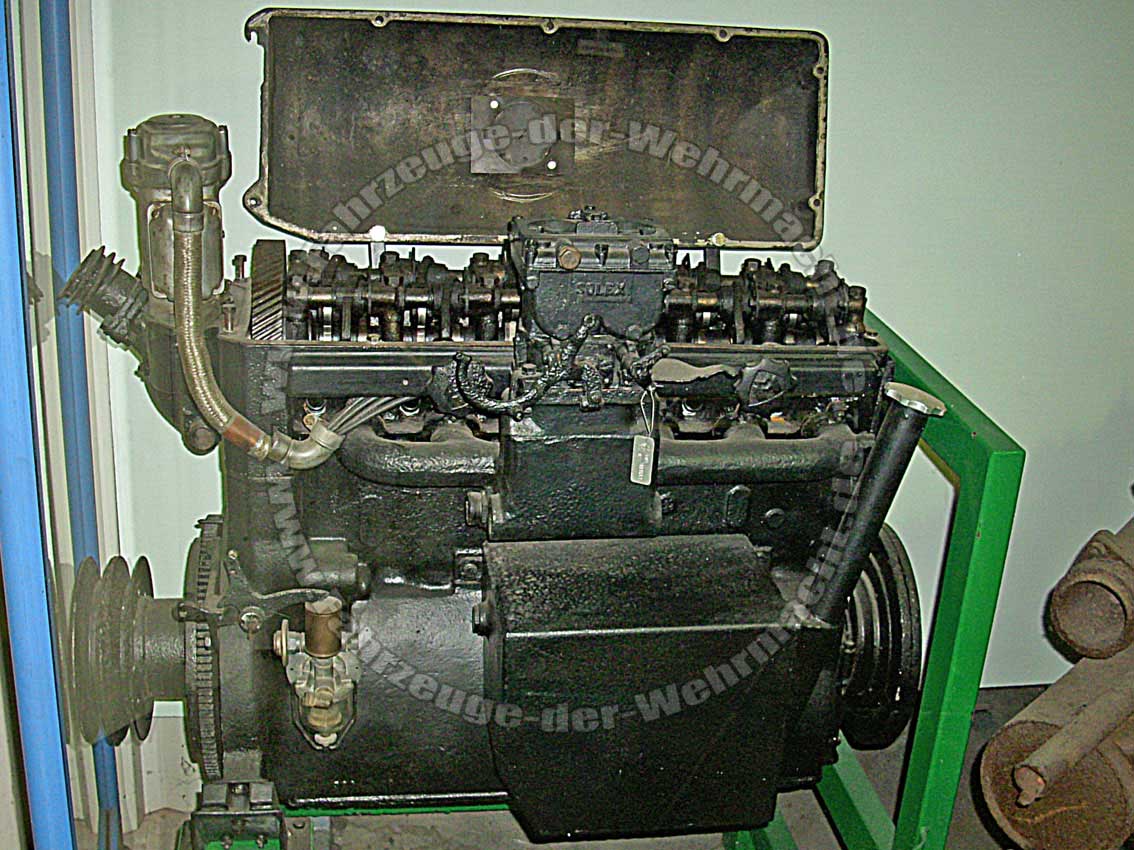
The 6-cylinder Maybach engines used a single Solex 40 JFF II down-draught carburetor,[21] and earlier V-12s used two.[22] Later V-12s used Solex 52 JFFs.
A hand-cranked inertia starter (Schwungkraftanlasser) was fitted to the V-12 engines to supplement the Bosch electric starter motor.[23]
Nomenclature
Introduction
Maybach used a series of letter codes and numbers to identify specific engine models, namely:
- NL / HL – performance
- TU / TR – lubrication
- K – clutch
- R / RR – belt drives for compressor and fans
- M – magneto ignition
Although these codes usually indicate what ancillary equipment was fitted at the factory (e.g. the HL42 TUKRRM and the HL57 TR), there are some exceptions, discussed below.
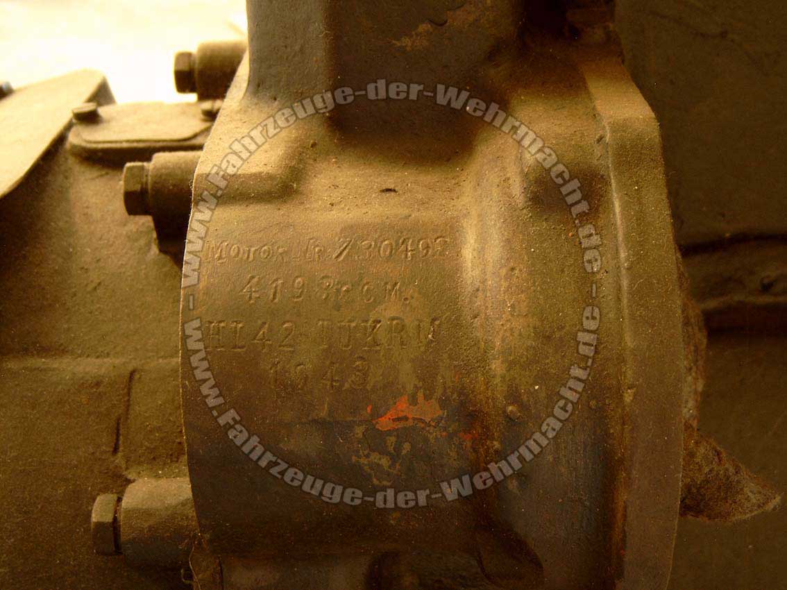
The individual engine number and its capacity, the model type, and year of manufacture are hand-stamped on each crankcase. On 6-cylinder models with magneto ignition, this information is found on the magneto housing: e.g.[24]
MOTOR Nr 730192

    4198 ccM.

   HL42 TUKRM

      1943
DSO8
An exception to the naming system outlined above is the V-12 DSO8 fitted to early Sd.Kfz. 8s. John Milsom mentions two versions, one with a power output of 150bhp fitted to the prototype DB ZD5 as early as 1931, and one of 200bhp found in the early production DB s 7 from 1934-6.[25] Further details, including the actual engine capacity, seem scarce.
The DSO8 also powered three Swedish Stridsvagn m/31 prototypes in the early 1930s. A 150hp DSO8 is also found in the Strv FM/31 Landsverk L-30 dating from 1931, examples of both are preserved in the Arsenalen Försvarsfordonsmuseum in Strängnäs, central Sweden.[26][27][lower-alpha 5]
Performance
- NL = Normalleistung (normal performance motor)
- HL = Hochleistung (high performance motor)
This is followed (without space) by the approximate engine capacity (e.g. HL42 = approx. 4.2 litres.)
Lubrication
- TR = Trockensumpfschmierung (dry sump lubrication), generally fitted to tanks - because of low ground clearance - and to the Sd.Kfz. 10 and 250 half-tracks. There is no sump below the crankcase: the engine oil is contained in a tank on one side. On later V-12s there is a tunnel through the oil tank, through which the hand crank for the inertia starter passes, operated from the outside rear of the vehicle.[28]
- In a number of cases, especially the dry sump tank engines (e.g the HL108 TR), this is the complete designation of an engine: in other words, there is no factory-fitted clutch (K) attached to the engine; no extra drive belts driving a compressor (R) and/or dual fans (RR) on custom pulleys; ignition is achieved via a distributor rather than a magneto (M); and no specific vehicular installation (P, S, or Z) is implied.[lower-alpha 6]
- TU = Tiefer Unterteil ('deep lower part' i.e. wet sump), only fitted to some half-tracks. The sump has an inverted triangle shape, bolted to the underneath of the crankcase housing.
- Most of the TU (wet sump) type engines were installed in half-track artillery tractors Sd.Kfz 6, 7, 8, 9 and 11, and were fitted with some or all of the ancillaries (K, R, or M). There appear, nevertheless, to be exceptions. For example, the HL57 TU was apparently only installed in some versions of the Sd.Kfz. 7, which was in fact fitted with a factory clutch, compressor and magneto. But since it was the only model available in that engine size, the extra equipment was fitted as standard and the extra letter codes were not included in the model number.[lower-alpha 7]
In addition, 'T' by itself has no meaning; it is always directly followed by either R or U, but 'R' in this position should not be confused with an (R) signifying a belt drive (see below). Furthermore, in some sources engines may be referred to simply as e.g. "a Maybach HL 120 of 300 metric horsepower", which indicates that further information is needed to identify the particular model number.
Transmission
- K = Kupplung or Kupplungsgehäuse (clutch housing): a clutch is attached directly to the flywheel end of the crankshaft, generally driving a manual 4-speed gearbox. This type of transmission was fitted to all the half-tracks with a TU-type engine,[29] and to early Panzer Is. The gearbox could also have a rear power take-off shaft fitted, to power a turntable for either a gun, or a winch or crane on e.g. the Sd.Kfz. 9/1.[30] The Sd.Kfz. 10 had a unique arrangement with a conventional clutch attached to the engine driving a pre-selector VG102 128H gearbox.[31] See also § Compressor below.

- If there is no factory-fitted clutch (K), this indicates a tank engine (except early Panzer Is). Instead, a horizontal cardan shaft connects the flywheel to a separate gearbox next to the driver. This could be a pneumatically-controlled, pre-selector Maybach-Variorex (e.g. certain Panzer IIIs and Stug III); or a synchromesh ZF Aphon (e.g. later Panzer III and IVs); or a hydraulically-controlled Maybach-Olvar (e.g. Tiger I and II).
- A 10-speed Maybach-Variorex SRG 328 145 gearbox[lower-alpha 8] was fitted in Panzer IIIs Ausf. E–G,[32] operated by vacuum pressure generated by a compressor (R) - see next section. The main clutch is integral to the gearbox housing.[33] (See also diagram on right.)
- Other tank gearboxes included the synchromesh ZF Aphon SSG[lower-alpha 9] 5x and 7x series gearboxes (the SSG 75 fitted in early Panzer IV had five forward gears and one reverse:[34] the 76 and 77 had six forward and one reverse). The main clutch (Hauptkupplung) (LA 120 HD) was bolted to the gearbox on the SSG 75, and incorporated into the main housing in the 77.[35] The SSG 77 gearbox replaced the mechanically vulnerable Variorex in the Stug. III Ausf. C.[36][37] Bigger tank engines (e.g. the HL230) used a hydraulically-controlled Maybach-Olvar gearbox such as the Olvar EG 40 12 16 (8 forward gears, 4 reverse), fitted to Tiger Is and IIs.[38][39][40]
- Some half-track gearboxes also included a power take-off shaft (PTO) driving an external winch (German: Seilwinde).[lower-alpha 10]
Compressor
- R = Riemenantrieb für Luftpresser (belt drive for air compressor), driven by a pulley at the other end from the flywheel. The compressor is connected to various types of equipment, including:
- Panzer III and Stug III (some variants) – Maybach Variorex SRG 328 145 pre-selector gearbox
- Sd.Kfz. 10 and 250 – Variorex VG 102 128H pre-selector g/box
- Sd.Kfz. 11 and 251 – air brakes on towed equipment (e.g. Pak 40 anti-tank gun)
- Sd.Kfz. 6–9 – pneumatic foot/parking brake + towed equipment[41] (e.g. 15 cm sIG 33 towed by the Sd.Kfz 7[42])
- On certain Panzer IIIs, and Stug III, and on the Sd.Kfz. 10 with its derivative the Sd.Kfz. 250, the compressor provided the (reverse) pressure for a pneumatically-operated pre-selector gearbox. To shift gears, the pre-selector lever is set in the desired position or slot, and then the clutch pedal is depressed and released. The air inlet of the compressor is connected to the system, not the outlet: the compressor works "in reverse" to create a vacuum. Inside the Variorex gearbox, there are vacuum-actuated pistons: these move dog clutches, which select the desired gearing.[33] On inline-6 engines, the compressor is mounted in various locations - either on the left or right at the front of the engine, or on top of the cam cover nearest the driver.
- KR = Clutch and compressor: production versions of the Demag half-tracks, the Sd.Kfz. 10 (manufacturer type D7) and Sd.Kfz. 250 (D7p) were fitted with a Maybach SRG, type VG 102 128H,[lower-alpha 11] with 7 forward and 3 reverse gears.[29][43][44] Although they worked on the same vacuum principle as the bigger tank pre-selector gearboxes, these types had no integral clutch, and were much smaller than those fitted to tanks. The drive passed through a standard clutch attached to the engine via a cardan shaft into the gearbox: depressing and releasing the clutch pedal simultaneously disengaged the main clutch and actuated the vacuum pistons to engage the pre-selected gear ratio.[31][45][46]
- KRR = Clutch, compressor, and extra belt drives for radiator fans: fitted to a number of Sd.Kfz. 11 and 251 variants.[29] A triple V-belt pulley mounted at the top of the engine also drove the twin cooling fans mounted directly between the engine and the radiator.[47][lower-alpha 12]
Ignition
- M = Schnapper-Magnetzündung (impulse magneto ignition): some models had a Bosch 12-volt magneto for the ignition. On 6-cylinder engines, the magneto is geared to the starter ring on the flywheel.[21] On 12-cylinder engines the magnetos were located either on the camshaft ends, or between the cylinder heads, driven by a large internal helical-cut ring gear.[49]
- The alternative to a magneto was an ignition coil (German: Zündspule) connected to a vertically-mounted distributor (German: Zündverteiler), often driven from one end of the camshaft.[50]
- Most models were also fitted with a belt-driven dynamo for charging the batteries for the electric starter motor, lighting, etc. On 4- and 6-cylinder engines the dynamo was usually connected by a drive shaft to a separate coolant pump located close to the cylindrical oil cooler.
Installation
- P = Panzerkampfwageneinbau (tank installation)
- Z = Zerstörereinbau (tank destroyer installation)[lower-alpha 13]
- S = Schleppereinbau (military tractor installation)
These letters were only used on some models, e.g. HL42 TRKM S, HL45 Z, HL230 P30. The HL230 P30 was designed to be fitted in the Panther, whose prototype was the 30-ton class VK30.02; the HL230 P45 went in the Tiger, whose final 45-ton class prototype was numbered VK45.01.[51]
Examples
- NL38 TRKM = Normal performance 3.8 litre, dry sump, clutch, magneto
- HL62 TR = High performance 6.2 litre, dry sump, pre-selector gearbox (no K), no compressor (R), ignition coil & distributor (no M)
- HL108 TUKRM = High performance 10.8 litre, wet sump, clutch, compressor, magneto
Gallery
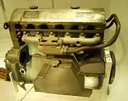 Maybach HL42 TRKM (intake side) with most ancillaries removed. Oil tank (TR dry sump) at lower centre; intake manifold and twin vertical holes for carburetter (centre); some of the clutch mechanism (K) partly obscured (far left); the magneto (M), driven off the flywheel, fits in the large hole to the left of the oil tank;[lower-alpha 14] the fuel pump attaches to the two threaded studs directly below.
 Maybach HL120 (flywheel end). Center top: black air cleaner, above twin Solex carburettors. Top right: the top of the 'compressor' and its driving pulley (partially obscured). Centre: camshaft cover with retaining knobs, above darker gray exhaust manifold. Lower right: vacuum tank or reservoir. Left lower centre: magneto.
.jpg.webp) Maybach HL120 TRM with cam cover cut away, showing helical-cut camshaft driving gear, and twin shafts carrying the rocker arms activated by the central camshaft (hidden).
Maybach HL120 TRM with cam cover cut away, showing helical-cut camshaft driving gear, and twin shafts carrying the rocker arms activated by the central camshaft (hidden).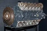 Maybach HL210 TRM P45. Note the right-angle shape of the cam followers, with rollers bearing on the camshaft lobes (partially visible just above the two leftmost inlet valve springs). The thin slotted brass guides are for setting the tappet clearances.[lower-alpha 15] The camshaft drive pinion has straight-cut teeth, which are noisier at high revs, but cheaper to manufacture.
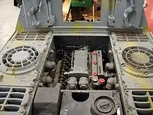
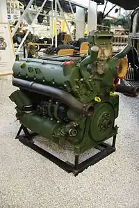 Maybach HL230, oil cooler side.[lower-alpha 16]
List of Maybach engines
| Model | Type | Capacity (Litres)[lower-alpha 17] | Power (PS)[lower-alpha 18] | @rpm[lower-alpha 19] | Application |
|---|---|---|---|---|---|
| HL25 | I-4 | 2.5 | 65 | 2,800 | Pre-production Sd.Kfz. 10 D4[3] |
| HL30 | I-4 | 3.0 | 95 | 3,000 | Le.WS - Leichter Wehrmacht Schlepper (Light Army Tractor) (1st & 2nd models)[52][53] |
| NL35 TUKM | I-6 | 3.435[lower-alpha 20] | 90 | 3,000 | Early Sd.Kfz. 6[54][lower-alpha 21] |
| NL38 TRKM[56] | I-6 | 3.817[lower-alpha 22] | 90 | 3,000 | Panzer I Ausf. B and derivatives, e.g. 15 cm sIG 33 (Sf) auf Panzerkampfwagen I Ausf B:[57] Sd.Kfz. 10 D6 (pre-production):[58] early Sd.Kfz. 11[59] |
| NL38 TUK | I-6 | 3.817 | 90 | early Sd.Kfz. 6 (BN 1 8) [60][61] | |
| HL38 TUKR | I-6 | 3.817 | 100 | 2,800 | Sd.Kfz. 11 (early versions)[62][lower-alpha 23] |
| HL42 TRKM | I-6 | 4.170[lower-alpha 24] | 110[59][lower-alpha 25] | Sd.Kfz. 10 type D7 (production models):[63][lower-alpha 26] | |
| HL42 TUKRR[64] | I-6 | 4.198 | 100 | Sd.Kfz. 11: Sd.Kfz. 251 (various models, incl. /16 & /21)[65] | |
| HL42 TUKRM | I-6 | 4.198 | 100 | 2,800 | Sd.Kfz. 250: Sd.Kfz. 11,[66] Sd.Kfz. 251 |
| HL42 TRKM-S[67] | I-6 | 4.198[lower-alpha 27] | 100 | 3,000 | Leichter Wehrmachtschlepper (Le.Ws) (late models) [52] Schwerer Wehrmachtschlepper (s.Ws)[68] |
| HL45 P | I-6 | 4.678 | 105[lower-alpha 28] | Panzer I Ausf. C/F and Ausf. J[69] | |
| HL45 Z | I-6 | 4.678 | 105[lower-alpha 28] | 2,800 | HKp 602/603 (prototype replacement for Sd.Kfz. 251)[70][71] |
| HL50 P | I-6 | 4.995 | 110[lower-alpha 29] | 3,000 | Kätzchen APC (prototype) · HKp 603/604 (later prototype replacement for Sd.Kfz. 251)[71] |
| HL52 TU[72] | I-6 | 115[lower-alpha 30] | Sd.Kfz. 7, 1st prod models[73] | ||
| HL54 TUKRM | I-6 | 5.420[lower-alpha 31] | 120?[lower-alpha 32] | 2,600 | Sd.Kfz. 6 (late models)[74] |
| HL57 TR | I-6 | 5.698 | 130 | 2,600 | Panzer II Ausf. a[75] |
| HL57 TU | I-6 | 5.698 | 130 | 2,600 | Sd.Kfz. 7, 2nd batch[76] |
| HL62 TR/TRM | I-6 | 6.191 | 140 | Panzer II Ausf. b–F:[77] Wespe[78] | |
| HL62 TUK | I-6 | 6.191 | 140 | 2,600 | Sd.Kfz. 7, 3rd batch (KM m 10)[79] |
| HL64 | I-6 | 6.4? | 160 | Sd.Kfz. 7 after 1943 | |
| HL66 P | I-6 | 6.754 | 180? | 2,800 | Panzer II Ausf. G and L (Luchs):[80] Sd.Kfz. 165/1 |
| SHL66 | I-6 | 6.754 | Used in Pionierschnellboot[51][81][lower-alpha 33] | ||
| OS6 | I-6 | 6.995[82][lower-alpha 34] | 90/95 | 1800/ 1900 | Krauss-Maffei KMS 85/100 (4-wheeled tractor)[82] |
| HL80[lower-alpha 35] | I-6 | 8.0? | 160? | 2,600 | Sd.Kfz. 7 (KM m 12 - 1939 projected design only)[76] |
| HL85 TUKRM | V-12 | 8.505[83] | 185 | 2,500 | Sd.Kfz. 8[84] |
| HL90[lower-alpha 36] | V-12 | 9.0[lower-alpha 37] | 200?[lower-alpha 38] | 3,000? | Heuschrecke 10 - Grasshopper SPG[85] |
| HL98 TUK | V-12 | 9.780[lower-alpha 39] | 220 – 250[lower-alpha 40] | 2,600/ 3000 | Early Sd.Kfz. 9 (FAMO F2 1938)[25] |
| HL100 TR | V-12 | 10.0[lower-alpha 41] | 250 | Panzer IV Ausf A [87][lower-alpha 42] | |
| HL108 TR | V-12 | 10.838 [lower-alpha 43] | 230 – 270 [lower-alpha 44] | 2,600/ 3,000 | Panzer III Ausf. A through D:[88] Panzer IV Ausf. A (only 35 made)[89] Stug III[90] |
| HL108 TUKRM | V-12 | 10.838 | 250 | 3,000 | Sd.Kfz. 9 (production models)[91] |
| HL116 Z | I-6[86][lower-alpha 45] | 11.048[lower-alpha 46] | 265[86][lower-alpha 47] | 3,300[86] | Sturer Emil : HK1600/1601/1604 (prototypes)[86][92] |
| HL120 TR | V-12 | 11.867 | 300 | 2,000 | Panzer III, Ausf. E:[32] StuG III Ausf. A:[36] Panzer IV Ausf. B, early C[32][87] |
| HL120 TRM112 | V-12 | 11.867 | 300 | Panzer III, Ausf. F-N:[93] StuG III: StuG IV: Hummel: Panzer IV Ausf. later C-J:[94] Elefant: Brummbär (Sturmpanzer IV) | |
| HL157 P[lower-alpha 48] | V-12 | 15.580 | 410? | 3,000? | VK 1602 Leopard (prototype) |
| HL174 | V-12 | 17.4[lower-alpha 49] | 450[95] | 3,000 | VK 3601 H (Henschel prototype)[95] |
| HL210 P30 | V-12 | 21.353[96] | 650 | 3,000? | First 250 Panther Ausf. Ds (aluminium alloy cylinder block)[97][98] |
| HL210 TRM P45 | V-12 | 21.353 | 650 | 3,000 | first 250 Tiger Is (aluminium alloy cylinder block)[99] |
| HL224 | V-12 | 22.4 | 680?[lower-alpha 50] | 3,000 | VK 6501(H), (heavy tank prototype by Henschel based on Panzer IV) |
| HL230 P30[97][100] | V-12 | 23.095[101] | 700 | Later Panther Ausf. Ds, all As and Gs[102] Jagdpanther, Tiger II (King Tiger),[103] : Jagdtiger : Sturmtiger : Panther II (prototype)[103] | |
| HL230 P45 | V-12 | 23.095 | 700 | 3,000 | Later versions of the Tiger I and Sturmtiger (cast iron block)[99] |
| HL234[lower-alpha 51] | V-12 | 23.88 | 900 | 3,000 | Panther II (proposed at later prototype stage, discontinued)[104] |
| HL295 | V-12 | 29.5[lower-alpha 52] | c.1000 | Post-war AMX-50 prototype.[105][106][lower-alpha 53] | |
Development of the HL210 and HL230
%252C_Wartung.jpg.webp)
A proposed replacement for the Panzer IV had been considered since around 1937. What became the Tiger tank went through a series of specifications, with the final revision (VK 4501) being made in May 1941.[107] Only a month later, the German armies invading Russia encountered the superior T-34 and KV-1: by December 1941 a specification for a 30-ton medium tank (which became the Panther) had been proposed as an immediate response to the Soviet tank threat.[108][lower-alpha 54]
Development of the two tanks continued simultaneously: the Tiger prototype was demonstrated to Hitler on his birthday in April 1942,[112] and the first of two Panther prototypes was ready in August 1942.[108]
The weight of the Tiger had increased considerably since its inception, and although it was now considerably heavier than the Panther medium tank, Maybach proposed fitting almost exactly the same 21-litre V-12 650 hp engine in both tanks. To save weight, the cylinder block was cast in aluminium alloy, with cast iron liners. The pistons were made of low-expansion aluminium-silicon alloy with Si content of nearly 20%.[113] The engine for the original 30-ton Panther project was the Maybach HL210 P30,[97] while the 45-ton specification for the Tiger received the HL210 P45.[99] The only visible difference was the arrangement of the coolant ducts exiting the cylinder heads, since the Panther and Tiger had different flows through their radiators.[lower-alpha 55]
Quantity series production of the PzKpfw VI Tiger (Ausf. H) with the HL210 P45 engine began in August 1942,[112] and it is possible that production of the Panther's HL210 P30 was begun at much the same time. The first battalions to be equipped with the Tigers were the 502nd Heavy Panzer Battalion on the Eastern Front near Leningrad, and the 501st Heavy Panzer Battalion which was sent to Tunisia. Unfortunately, it swiftly became apparent that the Tiger was seriously underpowered, and the rush into production of the new engines meant that the inevitable design defects had not been ironed out. Nevertheless, when the new Tigers arrived in Russia, there was only one spare engine and one transmission for every 10 tanks. A critical lack of spare parts meant that most of them were out of commission within a short period.[16]
The first PzKpfw V Panthers (Ausf. D) were similarly ill-fated; series production began in January 1943, but when they arrived in Russia in the spring the faults (including the steering and leaking engine gaskets) were so egregious that the entire batch had to be returned to Germany.[7] A special plant for rebuilding the Panthers was established near Berlin.[7]
In the meantime, Maybach re-designed the HL210, replacing the alloy cylinder block with a traditional cast-iron one. Although there was no space for a physically larger engine, the cylinders were capable of being bored out without compromising the engine's integrity. The new HL230 23-litre engines were installed from May 1943 in the latest production Panthers as the P30, and in Tigers as the P45.[114][115][116][lower-alpha 57]
Despite all the changes, the up-engined Panther Ausf. A with the HL230 P30 (which didn't arrive in Russia until late 1943) suffered from over-heating, fires in the engine compartment and blown head gaskets.[17]
The head gasket problem was solved in August 1943 by pressing copper rings into grooves to seal the head. A new design of piston was fitted to the HL230 P45 which reduced the compression ratio slightly.[115] In November 1943 a governor was installed in the HL230 P45 which limited the maximum revs to 2,500 rpm, and the maximum speed under full load to 38 km/h (24 mph). Some new and rebuilt motors from October had faulty bearings installed causing frequent failures: improved bearings were installed in new HL230 P45s from January 1944.[117]
Maybach didn't separate the production statistics of the 210 from the 230. Altogether, production of both types amounted to 153 in 1942, 4,346 in 1943, and 1,785 HL230s up to April 1944. In late April 1944 an Allied bombing raid put the Maybach factory out of action for six months.[118] Production was transferred to the Auto Union factory in Chemnitz, which delivered 219 HL230 engines to Henschel in 1944. A total of 4,366 HL230s from April for Panthers and Tigers were delivered from April 1944 to 1945.[118]
- Identifying HL210 and HL230 types
- HL210: three air filters; magnetos are located separately at the end of each camshaft; on the oil cooler side the oil filter sits at a relatively upright angle, approx. 70°.
- HL230: two air filters: magnetos are located centrally in a twin housing between the cylinder heads; oil filter sits at approx. 45°.
- P30: the twin cast iron hot coolant ducts are symmetrical and visually similar, with separate feeds to l.h and r.h. radiators..
- P45: the coolant ducts are siamesed into a single pipe leading to the r.h. radiator.[99]
Half-tracks
German WWII half-track prime mover numbering may appear not to be strictly logical: the two smallest vehicles were introduced after most of the larger artillery tractors were in production.[119] In ascending order of engine size and therefore towing capacity, they were designed to tow the following:[120]
- Sd.Kfz. 10 (1-ton), 3.7 cm PaK 36 & 5cm PaK 38, and SP 2cm Flak 30
- Sd.Kfz. 11 (3-ton), 7.5 cm Pak 40 & 41, 10.5 cm leFH 18 and 15 cm sIG 33, 7.5 cm Flak. L/60, standard and Nebelwerfer ammunition trailers
- Sd.Kfz. 6 (5-ton), 10.5 cm leFH 18, 7.5 cm Flak. L/60. Mainly used as engineer/Pioneer equipment and personnel carrier[59]
- Sd.Kfz. 7 (8-ton), 8.8 cm Flak, 10 cm K.18, 15 cm sFH 18, 15 cm Kanone 18 (2 separate loads); SP for 3.7 cm Flak & 2cm Flakvierling
- Sd.Kfz. 8 (12-ton), 10.5 cm FlaK 38, 17 cm Kanone 18 and 21 cm Mörser 18 (2 separate loads)
- Sd.Kfz. 9 (18-ton), 24 cm Kanone 3 (5 separate loads), 35.5 cm Mörser (7 separate loads), 6 or 10-ton crane, or tank recovery
As Maybach designed new, more powerful engines, all these vehicle types received at least two and up to four different engine models during production of the latest batches. There remained the necessity of attempting to produce either spare parts or complete new engines, just to keep the older vehicles running.
See also
- Maybach HL230
- GT 101, BMW-based turboshaft engine project for German AFVs
References
- Notes
- The HL230 P30 can be identified by twin central magneto housings between twin coolant ducts (white interiors), and the oil filter at approx. 45°.
- (Müller-Hillebrand 1982, p. 21). The lead author of this pamphlet, General Burkhart Müller-Hillebrand worked in the Operational History (German) Section of the Historical Section of the US Army in Karlsruhe after the war, helping to write operational histories from the German point of view.
- For example, an official report in September 1943 on the state of various battalions under the command of Panzerjäger-Regiment 656 (including the 653rd Heavy Panzerjäger Battalion) stated that sixty complete HL120 engines (two per tank) were needed to bring the Ferdinand battalions up to strength.(Munch 2005, pp. 62–3) In a long list of other modifications, only two related to the engine: the fuel line needed shielding from the exhaust; and oil leaked onto the fan housing, both leading to fires in the engine compartment.(Munch 2005, p. 64) A total of only 91 Ferdinands were ever built.
- For example, up to five 18-ton Sd.Kfz. 9s were needed to haul an immobilised Ferdinand through the mire of the Eastern Front.[14]
- A number of photos and drawings can be found here: sp15 (12 March 2014). "Swedish Tanks – Part II: Strv m/31 & Strv fm/31". For The Record. Retrieved 28 January 2021.
- Similarly, the HL57 TR and HL62 TR with no ancillaries were only fitted in the Panzer II.
- Likewise, the bored-out HL62 TUK engines were also only fitted in the SdKfz 7; these also had a compressor (R), but this appears not to have been included in the model designation.
- SRG = Schaltreglergetriebe, 'shift regulator [or controller] gearbox'. Maybach changed the name from SRG to Variorex in 1939. (Spielberger 1994, p. 37).
- SSG =Schaltsynchronisiertegetriebe, 'shift synchronised gearbox'
- Diagram of Sd.Kfz. 9 geartrain at Spielberger 1994, p. 215. Key, from r.: Seilwinde – winch; Untersetzergetriebe – reduction gearbox; Gleiskette – track; Bremszylinder – [air]brake cylinder; Lenkbremse – steering brake; Lenkgetriebe – steering gear; Kupplung – clutch; Luftfilter – air filter; Triebrad – driving wheel; Fahrbremse – road brakes; Triebradenantrieb – drivewheel gearbox; Wechselgetriebe – change speed gearbox.
- VG = Variorex-Getriebe, 'Variorex gearbox'; H = Hohlachse, 'hollow axle'
- "Cette motorisation est redésignée avec une lettre R supplémentaire (R = ventilation séparée), donnant ainsi les NL38 TUKRR, NL38 TUKRRM et HL42 TUKRRM."[48] This roughly translates as 'separate (or forced) ventilation', Fremdbelüftung.
- Or perhaps Zondereinbau, special installation.
- The serial number stamped on the magneto housing appears to be
MOT 551253 - Note the guide positioning and excessive tappet clearance of the far right inlet valve.
- HL230. From top right: magneto housing, between hot coolant pipes (to radiator). Immediately below magnetos: fan drive housing (yellow interior) with locating hole for fan drive shaft (four bolts). Centre right: cast iron exhausts. Lower right: harmonic damper with splined centre. Far lower right, beneath yellow lifting eye: oil tank (partially hidden), with hole for inertia starter handle (hand crank).[28] Centre, below exhaust: dynamo (black). Lower centre: oil cooler, with cold water inlet (from radiator). Far lower left: oil filter (at 45°). Top centre: carburettor cover, with holes for twin air filters
- Manufacturer's figures were given in litres. Exact engine capacities may vary slightly due to different values of π (Maybach used 355÷113), conversion into US customary units, rounding errors, etc. Details of engines fitted to a small number of prototypes are often vague. To work out engine capacity:
Engine capacity in litres = (π/4 * bore2 (mm) * stroke (mm) * no. of cylinders) ÷ 1,000,000
eg The Maybach HL85 has a bore and stroke of 95mm x 100mm. Taking π as 355÷113 (Maybach's own value),
Engine capacity = (0.78539823 * 9,025 * 100 * 12) ÷ 1,000,000 = 8.505 litres. - Manufacturer's values for engine power were originally stated in PS (metric horsepower), which is approximately equivalent to imperial/US horsepower (1 hp = 1.04 PS, 0.7457 kW). Stated figures in various sources can vary considerably, and
- These are manufacturer's maximum rpm figures: under normal operating conditions, recommended revs were a couple of hundred rpm less - e.g. 2,600 rather than 2,800 rpm. HL230s were governed to 2,600 rpm from 1943
- bore x stroke 90 x 90mm.[54]
- The compressor for the air brakes and towed equipment is mounted on top of the cam cover at the clutch end, possibly driven off the camshaft, which also drives the magneto.[55]
- Frank (Frank 1990, p. 4) gives 3.790 litres. This value is incorrect: Frank appears to have taken π as 3.12, thus with bore x stroke = 90 * 100 mm: 3.12/4 = 0.78, * (8,100 * 100 * 6) / 1,000,000 = 3.790. Taking Maybach's value of π as 355÷113, and bore x stroke of 90 * 100 mm, the correct value is 3.817 litres.
- A 100 hp Maybach engine was experimentally used in early Schnellbooten nos. S2–5 as an auxiliary power source which could operate the central propeller for silent running, but was found not to be needed. Source: Paterson, Lawrence (2015). Schnellboote: A Complete Operational History. Barnsley, Yorkshire: Seaforth Publishing. p. 24. ISBN 9781848320833.
- (Frank 1990, p. 4). This value is incorrect. Frank appears to have taken π as 3.12, thus: 3.12/4 = 0.78, * (8,100 * 110 * 6) / 1,000,000 = 4.16988 = 4.170
- Possibly an error for 100
- The Sd.Kfz. 10 chassis had a hull like a tank, (unlike the other half-tracks which had a frame chassis), and therefore used a dry sump (TR) engine because of the engine bay's restricted height.
- The figure 4.198 litres (taken from the manual) is arrived at by taking π as 355 ÷ 113, and bore * stroke = 90 x 110 mm (from the manual) : capacity = (0.78539823 * 8,100 * 110 * 6) / 1,000,000 = 4.198 litres.
- Some sources claim 150 PS/hp, but 105 PS/hp seems more likely, given its place in the hierarchy.
- Some sources put the figure as high as 150 or 180 PS, but these figures seem unlikely,
- Adjusted estimate
- bore * stroke = 100 x 115 mm.[54]
- Adjusted estimate. Sawicki & Ledwoch 2007, p. 53 state 84.6 kW (115.0 PS)
- This may be a similar engine to one described as a "6-cylinder Maybach S5 of approx. 7 litres", used to power motor boats used in bridging and rafting operations. See US War Department Technical Manual TM-E 30-451: Handbook on German Military Forces (March 1945), Chapter 8, p. VIII-93. The power output of 80 hp seems to be a misprint for 180.
- Bore x stroke = 94*168, compression ratio=1:5.7. Engine capacity in litres = (π/4 * bore2 (mm) * stroke (mm) * no. of cylinders) ÷ 1,000,000. Maybach used π=355÷113.
(0.78539823 * 8836 * 168 * 6) ÷ 1,000,000 = 6.995 - Prototypes only?
- Only three prototype Heuschrecke vehicles were ever constructed, 1942-3. Details are vague. Photos of engine at "Maybach Motoren: Maybach HL 90". Fahrzeuge der Wehrmacht (in German). Retrieved 12 May 2020.
- Approx. capacity based on the model number
- Various websites sources claim it was 300 or 360 hp, but these are not backed up by reliable printed sources.
- bore * stroke = 95 x 115mm.[86]
- Spielberger 1993, p. 165 gives 220 PS @ 2600 rpm, and 250 PS @3000 rpm from later models. Milsom 1975, p. 13 states 230.
- According to engine designation
- According to Anderson 2021, p. 33, the Ausf A was in production from June 1936 to November 1937.
- bore * stroke = 100 x 115 [86]
- Spielberger 1994, p. 21 gives 230 PS @ 2600 rpm: and 270 PS @ 3000 rpm in Spielberger 1993, p. 165, quoting his sources from original documents. Perrett 1980, p. 5 states 250 PS.
- Developed in 1941-2 for the Entwicklung series of new generation tanks, and new halftracks.
- bore * stroke = 125 x 150mm[86]
- Spielberger unfortunately contradicts himself on p. 86, saying it developed 300 PS. Milsom 1975, p. 62 states 250 PS.
- This engine and the HL174 appear only to have been fitted in a few prototypes, and there seem to be few reliable sources about them.
- Some sources claim 19.144 litres, but this figure should be around 17.4 litres according to the manufacturer's designation
- Adjusted estimate
- Fuel injection engine, due to be completed by August 1945
- from model number
- One example, captured in Friedrichshafen at the end of the war was tested in a post-war French AMX-50 heavy tank prototype. Weighing 57 tonnes, it failed to live up to expectations, with a road speed of 51 km/h, and only 20 km/h cross-country.[105]
- Although the T-34 and KV tanks were almost impervious to the German 37mm anti-tank guns and the guns of the Panzer III and IVs,[109] they were not the primary reason why the German offensive ground to a halt by the end of 1941. Both sides suffered huge losses of personnel and matériel. The Battle of Smolensk delayed the German push towards Moscow.[110] Despite staggering losses including the Battle of Bryansk, the Red Army (backed up by physical defences constructed by innumerable civilian forces, both women and men, and the implacable weather - the rasputitsa) kept the invading forces at bay for long enough to keep re-located tank production going over the winter.[111]
- The HL210 P30 is externally almost identical to the HL210 P45, apart from the hot coolant ducts (to radiator) at the flywheel end. On the P30 they are visually similar mirror images, and each duct is separately piped to the radiators on either side. On the P45 they are of unequal appearance, and are linked over the top of the fan drive housing into a 'Y'-fitting: a single pipe feeds the top of the offside radiator, which is coupled at the bottom to the top of the nearside radiator. The lower outlet of this feeds the oil cooler and then the water pump at the flywheel end. Photos make this much clearer.[97][99]
- The four large central grey fittings are ducts to improve air flow in the engine bay.
- The different cooling duct arrangements were carried over to their respective vehicles, and both designs received central twin magnetos, a new placement of the oil filter, and twin air filters in place of the triple cyclone housings.
- Citations
- Frank 1990, p. 20.
- "Maybach NL 38 und HL 42 Motor TUKRR TUKRM TRKM TUKRRM Ersatzteilliste". classicseller.com (in German). Retrieved 12 May 2020.
- Milsom 1975, p. 88.
- "'Nordbau': Norddeutsche Motorenbau GmbH Niederschöneweide". Fotowiesel (in German). Archived from the original on 30 January 2021. Retrieved 29 November 2020.
- Müller-Hillebrand 1982, pp. 2-4.
- Müller-Hillebrand 1982, p. 4.
- Müller-Hillebrand 1982, p. 25.
- Müller-Hillebrand 1982, p. 21.
- Müller-Hillebrand 1982, p. 3.
- Müller-Hillebrand 1982, p. 28.
- Munch 2005, p. 172, 187.
- Ankerstjerne, Christian (9 April 2016). "Homeland Armor Maintenance". Panzerworld. Archived from the original on 14 January 2019. Retrieved 16 May 2020.
- Müller-Hillebrand 1982, pp. 19, 25.
- Munch 2005, pp. 138-9.
- Milsom 1975, p. 9.
- Müller-Hillebrand 1982, pp. 24-25.
- Jentz 1995, pp. 61–62.
- Müller-Hillebrand 1982, p. 43.
- Hughes & Mann 1999, p. 34.
- Photos of various front covers at "Maybach HL 62 TUK 6-cylinder Vergasermotor Owner's Manual Brochure". classicseller.com. Archived from the original on 30 January 2021. Retrieved 20 May 2018.
- Photo (with Solex carburetter above, and fuel pump below l.) at "Maybach Sechszylindermotor HL 42". flickr. Archived from the original on 30 January 2021. Retrieved 20 April 2018.
- Photos of Solex 40 carbs (end of page) at "Panzer IV Ausf.G (früh)". Rommelkiste.de (in German). Archived from the original on 15 May 2017. Retrieved 20 April 2018.
- Illustration in Koch 2000, p. 27.
- Maybach HL42 TUKRM engine number. Fahrzeuge der Wehrmacht (in German). Retrieved 21 May 2018. Photo hosted at Fahrzeuge der Wehrmacht Archived 2021-01-30 at the Wayback Machine.
- Milsom 1975, p. 13.
- "Arsenalen Försvarsfordonsmuseum". Arsenalen Försvarsfordonsmuseum (in Swedish). Archived from the original on 24 July 2020. Retrieved 28 January 2021.
- Photos on Wikimedia Commons: Landsverk L-30
- Hand-cranking various tanks Archived 2020-02-28 at the Wayback Machine (Youtube)
- "Comparative table of various types of German half-tracked vehicles". TM-E 30-451: Handbook on German Military Forces. (Online version hosted at LoneSentry.com). U.S. War Department. 1945. Archived from the original on 6 December 2019. Retrieved 11 May 2020.CS1 maint: others (link)
- See Lubrication chart and photos of the model build at FAMO - Schwerer Zugkraftwagen 18 t - SdKfz 9 - Crane and cargo version Archived 2019-11-27 at the Wayback Machine by Panzerserra, retrieved 10 December 2019.
- Good cutaway diagram here: "Автострадные танки… по-немецки" [Avtostradnye tanki... po-nemetski]. Warspot.ru (in Russian). Archived from the original on 3 August 2020. Retrieved 11 May 2020.
- Koch 2000, p. 20.
- Photos, diagrams (some in English) and explanations here: "О крайней упоротости Pz.III ausf.E-G. Почему Pz.III ausf.E-G упороты (Flaws in the Panzer III ausf. E-G)". Kedoki (in Russian). Archived from the original on 19 February 2018. Retrieved 21 April 2018. (Russian website, but machine translation is not too bad these days).
- Perrett 1999, p. 5.
- Spielberger 1994, diagrams p.36; 40.
- Anderson 2016, p. 25.
- Spielberger 1994, p. 40.
- Jentz Doyle 2000, p. 32.
- Photos at "Tiger II Maybach Olvar EG 401216 B transmission unit". stalker6delta.tumblr.com. Archived from the original on 18 July 2019. Retrieved 17 July 2019.
- Diagrams and explanations here: Hamby, Alan. "Transmission & Steering". Tiger I Information Centre. Archived from the original on 4 June 2020. Retrieved 11 May 2020.
- Many detailed photos at Lebert, Ron. "Sd.Kfz. 6/2 with 37mm Flak 36: air brake details". Missing-Lynx. Archived from the original on 30 January 2021. Retrieved 11 May 2020.
- "15 cm sFH 18 German field howitzer". Panzerserra Bunker. 10 March 2017. Archived from the original on 7 February 2020. Retrieved 12 May 2020.
- Jentz 2008, p. 3.
- Jentz 2009, pp. 8, 20.
- Milsom 1975, p. 10.
- Photos at Schwabe, W. (30 December 2019). "Surviving SdKfz.10 D7 Demag Half-Tracks" (PDF). Archived (PDF) from the original on 30 January 2021. Retrieved 11 May 2020. and Schwabe, W. (15 January 2020). "Surviving SdKfz. 250 Half-Tracks" (PDF). Archived (PDF) from the original on 26 November 2020. Retrieved 11 May 2020. (search both for
MM Park, La Wantzenau) - Ashley, Terry. "German WWII Maybach HL 42 TUKRM Engine". PMMS. Archived from the original on 7 November 2012. Retrieved 11 May 2020.
- Couderc, Nicolas (April–May 2010). "Les Sd.Kfz.251 Ausf. A, B, C et D". Véhicules Militaires Magazine (in French) (32): 18–19. Archived from the original on 30 January 2021. Retrieved 11 May 2020.
- Photo of damaged HL120 TRM: Koch 2000, p. 18
- Photo at "Maybach NL-38". Fahrzeuge der Wehrmacht (in German). Archived from the original on 30 January 2021. Retrieved 21 May 2018.
- "Which vehicles used the Maybach SHL 66 petrol engine?". Axis History Forum. Archived from the original on 30 January 2021. Retrieved 16 May 2020.
- Milsom 1975, p. 94.
- "Leichte Wehrmachtsschlepper Adler leWS". Achtung Panzer!. Retrieved 20 April 2018.
- Sawicki & Ledwoch 2007, p. 53.
- Sawicki & Ledwoch 2007, pp. 52-3.
- Photo at "Maybach Motoren". Fahrzeuge der Wehrmacht (in German). Archived from the original on 29 May 2018. Retrieved 20 May 2018.
- Perrett 1998, pp. 6,8.
- Milsom 1975, pp. 10, 88.
- Milsom 1975, p. 11.
- Milsom 1975, pp. 11-12.
- "m. Zgkw. 5t (Sd. Kfz. 6): Medium Semitrack Prime Mover". Catalog of Enemy Ordnance Materiel, Volume 1: German. pp. 52, 53. lonesentry.com. Retrieved 22 April 2018. [NB includes pages missing/redacted from archive.org's copy of CoEO (G) 1945.]
- Milsom 1975, pp. 11, 90.
- Milsom 1975, pp. 88-89.
- Photo at "Mittlerer gepanzerter Mannschaftstransportwagen (Sd.Kfz. 251) Typ Hkl 6p". wh-verstand.de (in German). Archived from the original on 22 September 2018. Retrieved 21 May 2018.
- CoEO (G) 1945, p. 46•1 [pdf 28].
- Milsom 1975, pp. 90-91.
- Photos of 1943 manual: "Mittlere Zugkraftwagen 5t (Sd.Kfz. 6)". wh-versand.de (in German). Archived from the original on 18 April 2018. Retrieved 20 April 2018. bore * stroke: 90 x 110 mm, 4.198 litres, compression ratio 1:6.6
- Milsom 1975, p. 75.
- Perrett 1998, pp. 6-7.
- "HKp 602/603". Achtung Panzer!. Retrieved 20 April 2018.
- "HKp 602 / 603, HKp 605 / 606". Vehicles of the Wehrmacht 1939-1945. Archived from the original on 30 January 2021. Retrieved 16 August 2019.
- Photo at Milsom 1975, p. 40
- Milsom 1975, p. 92.
- Milsom 1975, pp. 12, 90.
- Perrett 1998, p. 9.
- Milsom 1975, pp. 12, 92.
- Perrett 1998, p. 9; plate D.
- Perrett 1998, p. 14.
- Milsom 1975, p. 12.
- Perrett 1998, p. 12.
- Photo at Kuhn 2017, p. 16
- Spielberger 1978, p. 198.
- Bore * stroke = 95mm x 100mm: see Sd.Kfz. 8 manual
- Milsom 1975, pp. 13, 92.
- "Heuschrecke 10". The Encyclopedia of Weapons of World War II. 1, p. 540. Sterling Publishing Company. ISBN 1-58663-762-2.
- Spielberger 1993, p. 165.
- Anderson 2021, p. 33.
- Perrett 1980, p. 5.
- Perrett 1999, pp. 5-6.
- Spielberger 1994, p. 21.
- Milsom 1975, p. 14.
- Milsom 1975, p. 62.
- Perrett 1980, pp. 6-9.
- Perrett 1999, p. 6.
- "King Tiger development". Swiss Military Museum Full. Archived from the original on 12 April 2018. Retrieved 20 April 2018.
- Bore * stroke 125 mm x 145 mm. Taking Maybach's value of π as 355÷113, engine capacity = (0.78539823 * 15,625 * 145 * 12) ÷ 1,000,000 = 21.353 litres.
- Tech. info and labelled diagrams at Eberl, E. (3 February 2015). "Motor & Transmission". Panther 1944 (in German and English). Archived from the original on 30 January 2020. Retrieved 14 February 2020.
- The intended HL230 P30 was not ready. (Doyle & Jentz 1997, pp. 5–6).
- "The Maybach Engine". The Tiger I Information Center. Archived from the original on 22 November 2018. Retrieved 8 January 2019.
- Informative labelled photos from Musée des Blindés, Saumur, at "The engine (HL230 P30)". Tiger1.info. Archived from the original on 4 November 2007. Retrieved 14 February 2020.
- Bore and stroke, 130 mm * 145 mm (5.1 in * 5.7 in) "German Armor Engines". PanzerWorld. Archived from the original on 23 January 2019. Retrieved 21 May 2018.
Taking Maybach's value of π as 355÷113, engine capacity = (0.78539823 * 16,900 * 145 * 12) ÷ 1,000,000 = 23.095 litres. - Doyle & Jentz 1997, pp. 6, 7, 8.
- Jentz & Doyle 1993, p. 12.
- Doyle & Jentz 1997, p. 10.
- Mercillon n.d., pp. 26-7.
- Albrecht 1997, pp. 119-20.
- Perrett 1981, pp. 3-4.
- Doyle & Jentz 1997, p. 4.
- Zaloga 1994, pp. 14-15.
- Bellamy 2007, p. 240.
- Zaloga 1994, pp. 14-17, 18-21.
- Perrett 1981, p. 4.
- Saeed et al. 2013, p. 640.
- Eberl, E. "The production periods of the Panther versions and the technical changes over the production periods". Panther 1944. Retrieved 16 May 2020. NB Engine changes half-way down in light grey.
- Jentz & Doyle 2000, pp. 75-6.
- Jentz & Doyle 2002, p. 14.
- Jentz & Doyle 2000, pp. 76.
- Jentz & Doyle 2000, p. 70.
- Milsom 1975, pp. 7-8.
- Milsom 1975, pp. 6-7.
Bibliography
- Albrecht, Ulricht (1997). "Rüstungsfragen in Deutsch-Französischen Verhältnis (1945-1960)". In Engler, Winfried (ed.). Frankreich an der Freien Universität: Geschichte und Aktualität. Zeitschrift für französische Sprache und Literatur, Issue 23 (in German). Stuttgart: Franz Steiner Verlag. ISBN 9783515069717.
- Anderson, Thomas (2016). Sturmartillerie: Spearhead of the infantry. Bloomsbury Publishing. ISBN 9781472811301.CS1 maint: ref=harv (link)
- Anderson, Thomas (2021). Panzer IV. Bloomsbury Publishing. ISBN 9781472829672.
- Bellamy, Chris (2007). Absolute War: Soviet Russia in the Second World War. New York: Vintage Books. ISBN 978-0-375-72471-8.
- Braithwaite, Rodric. Moscow 1941: A City and Its People at War. London: Profile Books Ltd., 2006. ISBN 1-86197-759-X.
- Catalogue of Enemy Ordnance Materiel. Volume 1: German. Office of the Chief of Ordnance. 1945.
- Doyle, Hilary L.; Jentz, Tom (1997). Panther Variants 1942-1945. illustrated by Michael Badrocke. Osprey/Reed Books. ISBN 9781855324763.CS1 maint: ref=harv (link)
- Frank, Reinhard, Dipl.-Ing. (1990). Leichte Zugkraftwagen der Wehrmacht im Einsatz: Eintonner - Dreitonner - Sonderaubuaten - Beutefahrzeuge. Waffen-Arsenal, Band 129 (in German). Friedberg, Hesse: Podzun-Pallas-Verlag. ISBN 9783790904192.CS1 maint: ref=harv (link)
- Hughes, Matthew; Mann, Chris (1999). The T-34 Russian Battle Tank. Wisconsin: MBI Publishing Company. ISBN 9780760307014.CS1 maint: ref=harv (link)
- Jentz, Thomas (1995). Germany's Panther Tank. Atglen, PA: Schiffer Publishing Ltd (US). ISBN 0887408125.CS1 maint: ref=harv (link)
- Jentz, Thomas L. (2008). Leichter Schutzenpanzerwagen: (Sd.Kfz. 250) Ausf. A and B: History of Production, Variants, Organization and Employment from 1941 to 1945. Panzer Tracts No. 15-1. Boyds, MD: Panzer Tracts. ISBN 978-0981538204.CS1 maint: ref=harv (link)
- Jentz, Thomas L. (2009). Leichter Zugkraftwagen 1 t: (Sd.Kfz. 10) Ausf. A and B and Variants: Development and Employment from 1935 to 1945. Panzer Tracts No. 22-1. Boyds, MD: Panzer Tracts. ISBN 978-0981538259.CS1 maint: ref=harv (link)
- Jentz, Tom; Doyle, Hilary (1993). Kingtiger Heavy Tank 1942-1945. illustrated by Peter Sarson. London: Osprey/Reed Books. ISBN 9781855322820.CS1 maint: ref=harv (link)
- Jentz, Thomas; Doyle, Hilary L. (2000). Gemany's Tiger Tanks: D.W. to Tiger I. Atglen, PA: Schiffer Military History. ISBN 0764310380.
- Jentz, Tom; Doyle, Hilary (2002). Tiger I Heavy Tank 1942 - 45. Illustrated by Peter Sarson. Osprey Publishing. ISBN 978-1855323377.CS1 maint: ref=harv (link)
- Koch, Fred (2000). Motoren Und Getriebe Deutscher Panzer 1935-1945. Waffen Arsenal 182 (in German). Wölfersheim-Berstadt: Podzun-Pallas-Verlag. ISBN 3790906956.CS1 maint: ref=harv (link)
- Kuhn, Michael (2017). Die Tübinger katholischen Theologiestudenten im nationalsozialistischen Arbeitsdienst 1933–1945: Anhang 1: Quellen und Materialien (PDF) (D. Phil. dissertation) (in German). Institut für Gesellschaftswissenschaften der Pädagogischen Hochschule Schwäbisch Gmünd. Retrieved 16 May 2020.CS1 maint: ref=harv (link)
- Mercillon, Patrick H. "AMX 50". Les Chars Français du Musée des Blindés (in French). Saumur, France: Centre de Documentation sur les Engins Blindés. pp. 26–27.
- Milsom, John (1975). German Half-tracked Vehicles of World War 2. London: Arms and Armour Press. ISBN 0882543547.CS1 maint: ref=harv (link)
- Munch, Karlheinz (2005). The Combat History of German Heavy Anti-Tank Unit 653 in World War II (illustrated, reprint ed.). Stackpole Books. ISBN 9780811732420.CS1 maint: ref=harv (link)
- Müller-Hillebrand, Burkhart H., Gen. (1982) [1954]. German Tank Maintenance in World War II (PDF). DA Pamphlets, No. 20-202 (Facsimile ed.). Department of the Army.CS1 maint: ref=harv (link)
- Perrett, Bryan (1980). Panzerkampfwagen III. Illustrated by David E. Smith and Mike Chapell. London: Osprey Publishing. ISBN 0850453623.CS1 maint: ref=harv (link)
- Perrett, Bryan (1981). The Tiger Tanks. Illustrated by David E. Smith. London: Osprey Publishing. ISBN 0850453895.CS1 maint: ref=harv (link)
- Perrett, Bryan (1998). German Light Panzers 1932-42. Illustrated by Peter Sarson & Terry Hadler (revised ed.). Oxford: Osprey Publishing. ISBN 1855328445.CS1 maint: ref=harv (link)
- Perrett, Bryan (1999). Panzerkampfwagen IV medium tank : 1936 - 1945. Illustrated by David. E. Smith & Jim Laurier (revised ed.). Oxford: Osprey Publishing. ISBN 9781855328433.CS1 maint: ref=harv (link)
- Saeed, Adil; Khan, Zulfiqar A.; Hadfield, Mark; Davies, Steve (July 2013). "Material Characterisation and Real Time Wear Evaluation of Pistons and Cylinder-liners of the Tiger 131 Military Tank". Tribology Transactions. 56 (4): 637–644. doi:10.1080/10402004.2013.771416. S2CID 53341629. Retrieved 19 June 2020.CS1 maint: ref=harv (link)
- Sawicki, Robert; Ledwoch, Janus (2007). Mittlere ZgKw 5t: Sd Kfz 6 (in Czech and English). Warsaw: Wydavnictwo "Militaria". ISBN 9788372192875.
- Spielberger, Walter (1978). Die Rad- und Vollketten Zugmaschinen des Deutschen Heeres 1870-1945. Scale drawings by Hilary L. Doyle. Stuttgart: Motorbuch Verlag. ISBN 978-3879435289.
- Spielberger, Walter (1993). Die Halbkettenfahrzeuge des Deutsches Heeres 1909–1945. Militarfahrzeuge Band 6 (in German). (Scale drawings by H.L. Doyle, colour illustrations by Uwe Feist) (4th ed.). Stuttgart: Motorbuch Verlag. ISBN 3879434034.
- Spielberger, Walter (1994). Sturmgeschütze: Entwicklung und Fertigung der sPak. Militärfahrzeuge, Band 13 (in German) (2nd ed.). Stuttgart: Motorbuch Verlag. ISBN 3613013568.CS1 maint: ref=harv (link)
- Zaloga, Steven J. (1994). T-34/76 Medium Tank 1941–45. (New Vanguard 9). Illustrated by Peter Sarson. Oxford: Osprey Publishing. ISBN 1855323826.
External links
- Photo gallery of various Maybach engine types at Fahrzeuge der Wehrmacht (in German), including NL38 TR, HL42 TRKM, HL54 TUKRM, HL62 TUK, HL85 TUKRM, HL90, HL108 TUKRM, HL120, HL230 P30 & P45, and fuel-injection HL295 fitted in post-war AMX-50 prototype