Müller-Breslau's principle
The Müller-Breslau principle is a method to determine influence lines. The principle states that the influence lines of an action (force or moment) assumes the scaled form of the deflection displacement. OR, This principle states that "ordinate of ILD for a reactive force is given by ordinate of elastic curve if a unit deflection is applied in the direction of reactive force."
This method is one of the easiest way to draw the influence lines.[1]
Example of using the Müller-Breslau principle to find qualitative influence lines

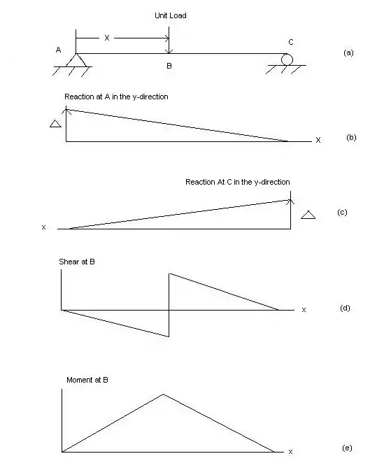
Part (a) of the figure to the right shows a simply supported beam with a unit load traveling across it. The structure is statically determinate. Therefore, all influence lines will be straight lines.
Parts (b) and (c) of the figure shows the influence lines for the reactions in the y-direction. Releasing the vertical reaction for A allows the beam to rotate to Δ. Likewise for part (c). Δ is typically taken as positive upwards.
Part (d) of the figure shows the influence line for shear at point B. Using the beam sign convention and cutting the beam at B, we can deduce the figure shown.
Part (e) of the figure shows the influence line for the bending moment at point B. Again making a cut through the beam at point B and using the beam sign convention, we can deduce the figure shown.
The procedure for applying the Muller-Breslau principle is as follows:
- Remove the constraint at the point of interest for the function of interest. This means if the influence line for a reaction is asked for simply start by pretending the beam is no longer attached to the reaction in question and is free to rotate about the other support. If the influence line for a moment is desired, pretend the point in question is a hinge and the subsequent two sides can rotate about their supports. If the influence line for shear is desired, again pretend the point in question is a shear release, again where both sides can rotate about their supports.
- Consider the remaining portion of the beam to have infinite rigidity, so it is a straight line free to rotate about the support.
- Lastly rotate whatever is free to rotate in its positive direction, but only enough to create a deflection of 1 unit total. This means if the moment IL is in question and an imaginary hinge is splitting the beam in two pieces, the two angles created between each rotated side and the original beam must add to equal 1. Similarly if the shear IL is in question the two sides will have opposite directions of rotation. So at the shear release the right side will typically be rotated upwards and the left side will be rotated downward, as this is the sign convention for shear. The total displacement between the two sides of the shear release must equal to 1.
References
- "6.3 Constructing Influence Lines using the Muller-Breslau Principle | learnaboutstructures.com". www.learnaboutstructures.com. Retrieved 2019-12-25.