Microtunneling
Microtunneling or microtunnelling is an underground tunnel construction technique used to construct utility tunnels from approximately 500mm to 4,000mm in diameter. Because these tunnels have an incredibly small diameter, it is not possible to have an operator driving the machine, so the tunneling machines have to be remotely operated from an operation panel within a purpose-built control room on ground level.[1]
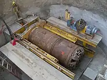
Microtunnel boring machines are very similar to normal tunnel boring machines (TBMs), but are of a reduced size. These machines generally vary from 0.65 to 4.0 meters (2 ft 2 in to 13 ft 1 in) but smaller and larger machines have existed. The machines are usually operated remotely from a control room on the surface. The Microtunneling machine and jacking frame are set up in a shaft at the required depth. The operator is given constant information about the location of the machine, orientation and hydraulic devices via a computer console, a CCTV camera or Gyro unit. Some systems have video cameras set up to enable the operator to monitor activities in the jacking shaft and at the separation plant. The operator controls the MTBM and the jacking frame from the safety of the control room which is usually situated on the surface, next to the jacking shaft. Later generation machines use Gyro Control location and digital feed back to the Operation panel.
In most microtunneling operations the machine is launched through an entry eye and pipes are pushed behind the machine. This is a process often called pipe jacking and is repeated until the Microtunneling machine reaches the reception shaft. As the machine advances, more tunnel liner or pipe is pushed from the starting shaft, through the entry eye. Thus, the speed of the advancing machine is controlled by the speed at which the pipe is inserted into the entry eye via the extension of the hydraulic rams in the jacking frame.
As the length of the tunnel increases, the friction of the ground around the pipe increases in proportion. Usually, two practices are used to minimize this friction. First, over-cutting is used to give a slight gap between the inner edge of the tunnel and the outer edge of the liner. Usually this is achieved by using a cutter wheel with a diameter ½ inch (12mm) to 1.5 inches (35mm) larger than the outside diameter of the liner. Secondly, a lubricant, often bentonite slurry, is injected into this gap. In addition to lubrication, the pressure of the lubricant prevents the gap from collapsing. In excess of a 35mm overcut it has been shown depending on the geology to create subsidence on top of the ground. For road and rail crossings, this 35mm is reduced so as not to allow more than 10mm subsidence.
Although friction can be reduced, it can never be eliminated, and sometimes hundreds of tons of force are required to push the machine and liner into the ground. A large “jacking frame” containing hydraulic rams is required to produce these forces. In most cases the entrance shaft must be strong enough to support the forces it generates.
In addition to the jacking frame, smaller jacks, called “interjacks”, may be inserted between sections of tunnel liner. These push the two sections of liner apart. Friction on the liner sections between the interjack and the tunnel entrance helps to prevent the liner from sliding out backwards. So while the liner behind the interjack does not move, those sections in front of it receive additional pushing force.