Necking (engineering)
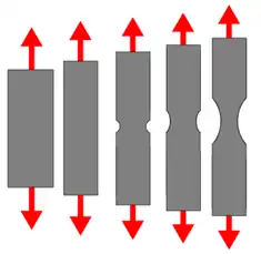
Necking, in engineering or materials science, is a mode of tensile deformation where relatively large amounts of strain localize disproportionately in a small region of the material.[1] The resulting prominent decrease in local cross-sectional area provides the basis for the name "neck". Because the local strains in the neck are large, necking is often closely associated with yielding, a form of plastic deformation associated with ductile materials, often metals or polymers.[2] Once necking has begun, the neck becomes the exclusive location of yielding in the material, as the reduced area gives the neck the largest local stress. The neck eventually becomes a fracture when enough strain is applied.

Formation
Necking results from an instability during tensile deformation when a material's cross-sectional area decreases by a greater proportion than the material strain hardens. Considère published the basic criterion for necking in 1885.[3] Three concepts provide the framework for understanding neck formation.
- Before deformation, all real materials have heterogeneities such as flaws or local variations in dimensions or composition that cause local fluctuations in stresses and strains. To determine the location of the incipient neck, these fluctuations need only be infinitesimal in magnitude.
- During tensile deformation the material decreases in cross-sectional area. (Poisson effect)
- During tensile deformation the material strain hardens. The amount of hardening varies with extent of deformation.
The latter two items determine the stability while the first item determines the neck's location.

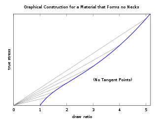
The plots at left show the quantitative relation between hardening (depicted by the curve's slope) and decrease in cross-sectional area (assumed in the Considère treatment to vary inversely with draw ratio) for a material that forms a stable neck (top) and a material that deforms homogeneously at all draw ratios (bottom).
As the material deforms, all locations undergo approximately the same amount of strain as long as it hardens more than its cross-sectional area decreases, as shown at small draw ratios in the top diagram and at all draw ratios in the bottom. But if the material begins to harden by a smaller proportion than the decrease in cross-sectional area, as indicated by the first tangent point in the top diagram, strain concentrates at the location of highest stress or lowest hardness. The greater the local strain, the greater the local decrease in cross-sectional area, which in turn causes even more concentration of strain, leading to an instability that causes the formation of a neck. This instability is called "geometric" or "extrinsic" because it involves the material's macroscopic decrease in cross-sectional area.
Neck stability
As deformation proceeds the geometric instability causes strain to continue concentrating in the neck until the material either ruptures or the necked material hardens enough, as indicated by the second tangent point in the top diagram, to cause other regions of the material to deform instead. The amount of strain in the stable neck is called the natural draw ratio[4] because it is determined by the material's hardening characteristics, not the amount of drawing imposed on the material. Ductile polymers often exhibit stable necks because molecular orientation provides a mechanism for hardening that predominates at large strains.[5]
Mathematical treatment
In the engineering stress strain curve, the onset of necking occurs at the curve's maximum, that is, the maximum applied load that the material can carry, or the Ultimate Tensile Strength. The load carried is given by
F = σT Ai
where σT is the true stress and Ai is the instantaneous area. At the maximum, the derivative of the force is equal to
dF = dσT Ai + σT dAi = 0
or
dσT/σT = -dAi /Ai
The criterion for necking is therefore that the incremental increase in internal stress is exactly equal to the incremental decrease in the cross sectional area where the stress is localized.[6]
References
- P.W. Bridgman, Large Plastic Flow and Fracture, McGraw-Hill, (1952)
- A.J. Kinloch and R.J. Young, Fracture Behaviour of Polymers, Chapman & Hall (1995) p108
- Armand Considère, Annales des Ponts et Chaussées 9 (1885) pages 574-775
- Roland Séguéla Macromolecular Materials and Engineering Volume 292 Issue 3 (2006) pages 235 - 244
- R. N. Haward J. Polym Sci Part B: Polym. Phys. 45 (2007) pages 1090-1099
- Courtney, Thomas H. (2000). Mechanical behavior of materials (2nd ed.). Boston: McGraw Hill. ISBN 0070285942. OCLC 41932585.