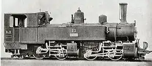
Rhaetian Railway G 2/2+2/3
The Rhaetian Railway G 2/2+2/3, was a two-member class of metre gauge Mallet-type steam locomotives manufactured by SLM in Winterthur, Switzerland, in 1896, and operated until 1926 by the Rhaetian Railway, in the Canton of Graubünden, Switzerland.
| Rhaetian Railway G 2/2+2/3 | |||||||||||||||||||||||||||||||||||||||||||||
|---|---|---|---|---|---|---|---|---|---|---|---|---|---|---|---|---|---|---|---|---|---|---|---|---|---|---|---|---|---|---|---|---|---|---|---|---|---|---|---|---|---|---|---|---|---|
 RhB 23 | |||||||||||||||||||||||||||||||||||||||||||||
| |||||||||||||||||||||||||||||||||||||||||||||
| |||||||||||||||||||||||||||||||||||||||||||||
| |||||||||||||||||||||||||||||||||||||||||||||
The two members of the class were so named under the Swiss locomotive and railcar classification system. According to that system, G 2/2+2/3 denotes a two-bogie narrow gauge steam locomotive, with the front bogie having two drive axles, but the rear bogie being fitted with three axles, only two of them drive axles.
The G 2/2+2/3 class locomotives differed from their two G 2x2/2 class predecessors, which had been delivered in 1891, in having the additional, non-drive, axle in the rear bogie, thus providing an extra set of wheels, under the driver's cab.
In 1903, in a follow up order of a further eight Mallet-type locomotives, this second chassis configuration was altered again, by reversing the order of the bogies and their wheel arrangement. The configuration of the 1903 locomotives therefore became G 2/3+2/2, with the single set of trailing wheels right at the front of the locomotive. The 1891 G 2x2/2 class locomotives were then rebuilt into the third configuration.
Technical details
The main rationale for locating the G 2/2+2/3 class's sole carrying axle in a position under the locomotive's cab was that it increased the locomotive's operating reserves. As the boiler and chassis dimensions remained essentially the same, only the boiler pressure was increased from 12 to 14 atms. Consequently, the high-pressure cylinder diameter was minimised, and the rather large rear overhang was reduced. However, it quickly became apparent that these changes did not improve the locomotive's ride quality, and that the locomotives caused similarly high flange and track wear as their predecessors. That was the basis on which the G 2/3+2/2 class was later built with a leading carrying axle instead of a trailing one.
The G 2/2+2/3 class had an external frame. The part of the chassis supporting the rear of the locomotive was pulled forward, and in the centre supported the rear bogie. The boiler was mounted forward of this point, and thus its rear was supported at fulcrum level. The locomotive had no pivot point, as a ball joint provided for steam injection. The bogie was connected with the chassis by pivot bearings, creating an articulated joint. In connection with this, there were two buffer springs, which, together with the centring springs of the mobile crosshead guides, counteracted any rolling of the bogie.
The carrying axle was in the form of an Adams axle. The rear cylinders were the high-pressure cylinders, which drew all of their steam directly from the centrally located steam dome. The front cylinders were fed with the exhaust steam of the high-pressure cylinders. Steam was supplied to the cylinders by fixed pipes, the ball joint of which was located in the pivot. The exhaust steam was led to the blast pipe via an articulated exhaust pipe fitted with stuffing boxes. To start the locomotive, the low-pressure cylinders could be supplied with low-pressure steam.
The two sets of valve gear were of identical Walschaerts design. Each set of valve gear was controlled by two overhead camshafts coupled and balanced with an inside rod. Reversing was achieved with a screw and wheel. With a fully open regulator, live steam was supplied to the low-pressure cylinders by an automatic throttle.
List of locomotives
| Number | Name | Manufacturer | Serial no. | Build year | Sold | Scrapped | Comments |
|---|---|---|---|---|---|---|---|
| 23 | Maloja | SLM | 958 | 1896 | 1926 | 1940 | scrapped |
| 24 | Chiavenna | SLM | 959 | 1896 | 1926 | 1937 | scrapped |
Service history
The performance specifications for the class as ordered required each locomotive to haul a train of 70 tonnes (69 long tons; 77 short tons) up a gradient of 4.5% at 15 kilometres per hour (9.3 mph). This target could be achieved with a power output of 370 kilowatts (500 hp).
The two locomotives in the class were withdrawn by the Rhaetian Railway in 1926, and sold to Kraftwerke Oberhasli (predecessor company of the Meiringen–Innertkirchen Bahn), which operated them under the same traffic numbers to 1940 (No. 23) and 1937 (No. 24). At the latest during World War II, the locomotives were transformed into scrap metal.
References
Literature
- Alfred Moser: Der Dampfbetrieb der Schweizerischen Eisenbahnen 1847–1966. 4th revised edition, Birkhäuser, Stuttgart 1967, 341 pages ff.(6th ed ISBN 3-7643-0742-0) (in German)
- Claude Jeanmaire: Die Dampflokomotiven der Rhätischen Bahn, Archive no. 22, 2nd ed, Verlag Eisenbahn, 1974, ISBN 3-85649-022-1 (Drawing/Pictures 306-311) (in German)
This article is based upon a translation of the German-language version as at August 2010.
