Rigid chain actuator
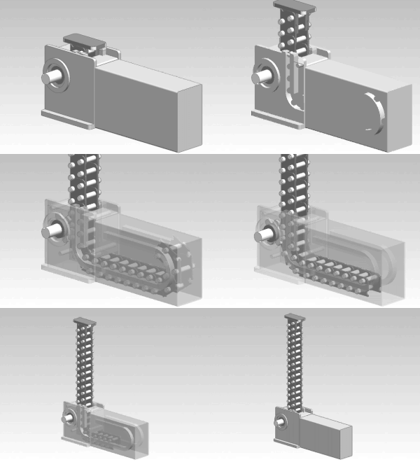
A rigid chain actuator, known variously as a linear chain actuator, push-pull chain actuator, electric chain actuator or column-forming chain actuator, is a specialized mechanical linear actuator used in window operating, push-pull material handling and lift applications. The actuator is a chain and pinion device that forms an articulated telescoping member to transmit traction and thrust. High-capacity rigid chain lifting columns (jacks) can move dynamic loads exceeding 10 tonnes (US 20,000 pounds) over more than 7 metres (20 feet) of travel.[1]

Principle of operation
Rigid chain actuators function as rack and pinion linear actuators that use articulated racks. Rigid chain actuators use limited-articulation chains, usually resembling a roller chain, that engage with pinions mounted on a drive shaft within a housing. The links of the actuating member, the “rigid chain”, are articulated in a manner that they deflect from a straight line to one side only. As the pinions spin, the links of the chain are rotated 90 degrees through the housing, which guides and locks the chain into a rigid linear form effective at resisting tension and compression (buckling). Because the actuating member can fold on itself, it can be stored relatively compactly in a storage magazine, either in an overlapping or coiled arrangement. Rigid chain actuators are generally driven by electric motors. Most rigid chains are manufactured from steel.
Use

Modified roller chain has been used extensively in material handling equipment, but could only be used in push-pull applications when a continuous loop of chain was used (with the exception of chain encapsulated in a guide channel). The development of efficient rigid chain actuators broadened the use of chain actuation for industrial applications. Small scale rigid chain actuators are used as building hardware, incorporated into windows, door and hatches as motorized open/close mechanisms.[2] Rigid chain actuators are also used as the lifting columns in performing arts facilities, incorporated in stage, orchestra and seating platform lift systems.
Increasingly rigid chain systems are being incorporated into scissor lift tables or platform lifts as the method of actuation, replacing hydraulic cylinders. They are also used for production line automation and die changing.
The autoloaders used in Soviet/Russian tanks such as the T-64, T-80, T-72 and T-90 use rigid chain systems to push the two-part ammunition (projectile and propellant) into the tank's gun.
Types
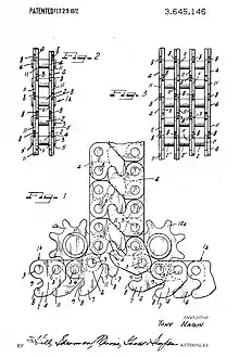
The primary distinction between types of rigid chain actuator is whether the actuating member is formed from a single chain or from a pair of interlocking chains in a back-to-back arrangement, like a zipper. Interlocking chain actuators have the advantages over single-chain actuators of improved resistance to buckling and that the actuating member does not require lateral restraint at its leading end in order to resist a modicum of transverse loads on any edge of the member. For example, it may function as a relatively stable telescoping pole.
The design of the chain varies significantly depending on application and manufacturer. Variants have been designed to, among other things:
- Simplify manufacture
- Reduce friction and maintenance
- Limit size and weight
- Increase speed, travel, capacity, efficiency and stability
Development

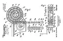
Rigid chain actuators were developed from “chain rammers” that used a single “ram chain” thrust from a magazine to load heavy-caliber ordnance into the breech of a cannon. Robert Matthews received a US patent for his “Mechanical Rammer” in 1901 which used a roller on the leading end of the chain to guide it and allow thrust without deflection.[3] Developed more than a century ago, his rammer still bears a strong resemblance to many modern rigid chain actuators. In 1908 Oscar Knoch was awarded a US patent for his “Chain Rammer for Guns”.[4] By orienting the folding side of the chain upward his ram chain acted as a self-supporting telescoping beam with negligible sag. Used in this manner the need for a separate guide was eliminated.
An early conception of chain used as a telescoping column instead a horizontal rammer was by Eldridge E. Long, who was awarded a US patent for his “Lifting Jack” in 1933, which he believed was “particularly adapted for use upon automobiles”.[5] It used a double chain configuration, each chain linking solid bearing blocks that were stacked to resist compressive loads. In 1951, Yaichi Hayakawa was awarded a US patent for his “Interlocking Chain Stanchion” which eliminated bearing blocks by integrating the compressive path of force into the interlocking links of two roller-like chains.[6] The zipper action of back-to-back interlocking chains provided guideless chain travel regardless of orientation and path of travel.
In 1941, prior to the double chain configuration, Karl Bender received a US patent for "Compression Resistant Chain" using three interlocking chains.[7] In addition to the back-to-back arrangement of the typical interlocking chain actuator, a third chain was interlocked between the other two at a right angle. Perhaps due to their relative complexity, triple-chain actuators are not common.
References
- Serapid lifting column brochure: http://serapid.us/PDF/Linear-Tele-Lifting-Col.pdf%5B%5D
- Teleflex window chain openers: "Archived copy". Archived from the original on 2010-04-26. Retrieved 2010-08-05.CS1 maint: archived copy as title (link)
- US 682100
- US 904966
- US 1925194
- US 2554300
- US 2375461
See also
- Linear actuator – Actuator that creates motion in a straight line
- continuously variable transmission#Push-Belt – Automatic transmission that can change seamlessly through a continuous range of effective gear ratios
- Rigid belt actuator