Scheimpflug principle
The Scheimpflug principle is a description of the geometric relationship between the orientation of the plane of focus, the lens plane, and the image plane of an optical system (such as a camera) when the lens plane is not parallel to the image plane. It is applicable to the use of some camera movements on a view camera. It is also the principle used in corneal pachymetry, the mapping of corneal topography, done prior to refractive eye surgery such as LASIK, and used for early detection of keratoconus. The principle is named after Austrian army Captain Theodor Scheimpflug, who used it in devising a systematic method and apparatus for correcting perspective distortion in aerial photographs; even though Captain Scheimpflug himself credits Jules Carpentier with the rule, thus making it an example of Stigler's law of eponymy.

Description
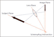
Normally, the lens and image (film or sensor) planes of a camera are parallel, and the plane of focus (PoF) is parallel to the lens and image planes. If a planar subject (such as the side of a building) is also parallel to the image plane, it can coincide with the PoF, and the entire subject can be rendered sharply. If the subject plane is not parallel to the image plane, it will be in focus only along a line where it intersects the PoF, as illustrated in Figure 1.
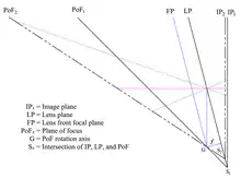
But when a lens is tilted with respect to the image plane, an oblique tangent extended from the image plane and another extended from the lens plane meet at a line through which the PoF also passes, as illustrated in Figure 2. With this condition, a planar subject that is not parallel to the image plane can be completely in focus. While many photographers were/are unaware of the exact geometric relationship between the PoF, lens plane, and film plane, swinging and tilting the lens to swing and tilt the PoF was practiced since the mid-1800s. But, when Carpentier and Scheimpflug wanted to produce equipment to automate the process, they needed to find a geometric relationship.
Scheimpflug (1904) referenced this concept in his British patent; Carpentier (1901) also described the concept in an earlier British patent for a perspective-correcting photographic enlarger. The concept can be inferred from a theorem in projective geometry of Gérard Desargues; the principle also readily derives from simple geometric considerations and application of the Gaussian thin-lens formula, as shown in the section Proof of the Scheimpflug principle.
Changing the plane of focus
When the lens and image planes are not parallel, adjusting focus[lower-alpha 1] rotates the PoF rather than merely displacing it along the lens axis. The axis of rotation is the intersection of the lens's front focal plane and a plane through the center of the lens parallel to the image plane, as shown in Figure 3. As the image plane is moved from IP1 to IP2, the PoF rotates about the axis G from position PoF1 to position PoF2; the "Scheimpflug line" moves from position S1 to position S2. The axis of rotation has been given many different names: "counter axis" (Scheimpflug 1904), "hinge line" (Merklinger 1996), and "pivot point" (Wheeler).
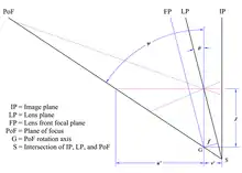
Refer to Figure 4; if a lens with focal length f is tilted by an angle θ relative to the image plane, the distance J[lower-alpha 2] from the center of the lens to the axis G is given by
If v′ is the distance along the line of sight from the image plane to the center of the lens, the angle ψ between the image plane and the PoF is given by[lower-alpha 3]
Equivalently, on the object side of the lens, if u′ is the distance along the line of sight from the center of the lens to the PoF, the angle ψ is given by
The angle ψ increases with focus distance; when the focus is at infinity, the PoF is perpendicular to the image plane for any nonzero value of tilt. The distances u′ and v′ along the line of sight are not the object and image distances u and v used in the thin-lens formula
where the distances are perpendicular to the lens plane. Distances u and v are related to the line-of-sight distances by u = u′ cos θ and v = v′ cos θ.
For an essentially planar subject, such as a roadway extending for miles from the camera on flat terrain, the tilt can be set to place the axis G in the subject plane, and the focus then adjusted to rotate the PoF so that it coincides with the subject plane. The entire subject can be in focus, even if it is not parallel to the image plane.
The plane of focus also can be rotated so that it does not coincide with the subject plane, and so that only a small part of the subject is in focus. This technique sometimes is referred to as "anti-Scheimpflug", though it actually relies on the Scheimpflug principle.
Rotation of the plane of focus can be accomplished by rotating either the lens plane or the image plane. Rotating the lens (as by adjusting the front standard on a view camera) does not alter linear perspective[lower-alpha 4] in a planar subject such as the face of a building, but requires a lens with a large image circle to avoid vignetting. Rotating the image plane (as by adjusting the back or rear standard on a view camera) alters perspective (e.g., the sides of a building converge), but works with a lens that has a smaller image circle. Rotation of the lens or back about a horizontal axis is commonly called tilt, and rotation about a vertical axis is commonly called swing.
Camera movements
Tilt and swing are movements available on most view cameras, often on both the front and rear standards, and on some small- and medium format cameras using special lenses that partially emulate view-camera movements. Such lenses are often called tilt-shift or "perspective control" lenses.[lower-alpha 5] For some camera models there are adapters that enable movements with some of the manufacturer's regular lenses, and a crude approximation may be achieved with such attachments as the 'Lensbaby' or by 'freelensing'.
Depth of field
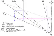
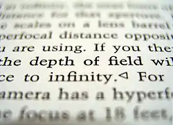
When the lens and image planes are parallel, the depth of field (DoF) extends between parallel planes on either side of the plane of focus. When the Scheimpflug principle is employed, the DoF becomes wedge shaped (Merklinger 1996, 32; Tillmanns 1997, 71),[lower-alpha 6] with the apex of the wedge at the PoF rotation axis,[lower-alpha 7] as shown in Figure 5. The DoF is zero at the apex, remains shallow at the edge of the lens's field of view, and increases with distance from the camera. The shallow DoF near the camera requires the PoF to be positioned carefully if near objects are to be rendered sharply.
On a plane parallel to the image plane, the DoF is equally distributed above and below the PoF; in Figure 5, the distances yn and yf on the plane VP are equal. This distribution can be helpful in determining the best position for the PoF; if a scene includes a distant tall feature, the best fit of the DoF to the scene often results from having the PoF pass through the vertical midpoint of that feature. The angular DoF, however, is not equally distributed about the PoF.
The distances yn and yf are given by (Merklinger 1996, 126)
where f is the lens focal length, v′ and u′ are the image and object distances parallel to the line of sight, uh is the hyperfocal distance, and J is the distance from the center of the lens to the PoF rotation axis. By solving the image-side equation for tan ψ for v′ and substituting for v′ and uh in the equation above,[lower-alpha 8] the values may be given equivalently by
where N is the lens f-number and c is the circle of confusion. At a large focus distance (equivalent to a large angle between the PoF and the image plane), v′ ≈ f, and (Merklinger 1996, 48)[lower-alpha 9]
or
Thus at the hyperfocal distance, the DoF on a plane parallel to the image plane extends a distance of J on either side of the PoF.
With some subjects, such as landscapes, the wedge-shaped DoF is a good fit to the scene, and satisfactory sharpness can often be achieved with a smaller lens f-number (larger aperture) than would be required if the PoF were parallel to the image plane.
Selective focus

The region of sharpness can also be made very small by using large tilt and a small f-number. For example, with 8° tilt on a 90 mm lens for a small-format camera, the total vertical DoF at the hyperfocal distance is approximately[lower-alpha 10]
At an aperture of f/2.8, with a circle of confusion of 0.03 mm, this occurs at a distance u′ of approximately
Of course, the tilt also affects the position of the PoF, so if the tilt is chosen to minimize the region of sharpness, the PoF cannot be set to pass through more than one arbitrarily chosen point. If the PoF is to pass through more than one arbitrary point, the tilt and focus are fixed, and the lens f-number is the only available control for adjusting sharpness.
Derivation of the formulas
Proof of the Scheimpflug principle
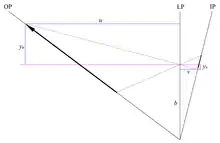
In a two-dimensional representation, an object plane inclined to the lens plane is a line described by
- .
By optical convention, both object and image distances are positive for real images, so that in Figure 6, the object distance u increases to the left of the lens plane LP; the vertical axis uses the normal Cartesian convention, with values above the optical axis positive and those below the optical axis negative.
The relationship between the object distance u, the image distance v, and the lens focal length f is given by the thin-lens equation
solving for u gives
so that
- .
The magnification m is the ratio of image height yv to object height yu :
yu and yv are of opposite sense, so the magnification is negative, indicating an inverted image. From similar triangles in Figure 6, the magnification also relates the image and object distances, so that
- .
On the image side of the lens,
giving
- .
The locus of focus for the inclined object plane is a plane; in two-dimensional representation, the y-intercept is the same as that for the line describing the object plane, so the object plane, lens plane, and image plane have a common intersection.
A similar proof is given by Larmore (1965, 171–173).
Angle of the PoF with the image plane
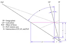
From Figure 7,
where u′ and v′ are the object and image distances along the line of sight and S is the distance from the line of sight to the Scheimpflug intersection at S. Again from Figure 7,
combining the previous two equations gives
From the thin-lens equation,
Solving for u′ gives
substituting this result into the equation for tan ψ gives
or
Similarly, the thin-lens equation can be solved for v′, and the result substituted into the equation for tan ψ to give the object-side relationship
Noting that
the relationship between ψ and θ can be expressed in terms of the magnification m of the object in the line of sight:
Proof of the "hinge rule"
From Figure 7,
combining with the previous result for the object side and eliminating ψ gives
Again from Figure 7,
so the distance d is the lens focal length f, and the point G is at the intersection the lens's front focal plane with a line parallel to the image plane. The distance J depends only on the lens tilt and the lens focal length; in particular, it is not affected by changes in focus. From Figure 7,
so the distance to the Scheimpflug intersection at S varies as the focus is changed. Thus the PoF rotates about the axis at G as focus is adjusted.
Notes
- Strictly, the PoF rotation axis remains fixed only when focus is adjusted by moving the camera back, as on a view camera. When focusing by moving the lens, there is a slight motion of the rotation axis, but except for very small camera-to-subject distances, the motion is usually insignificant.
- The symbol J for the distance from the center of the lens to the PoF rotation axis was introduced by Merklinger (1996), and apparently has no particular significance.
- Merklinger (1996, 24) gives the formula for the angle of the plane of focus as
- Strictly, keeping the image plane parallel to a planar subject maintains perspective in that subject only when the lens is of symmetrical design, i.e., the entrance and exit pupils coincide with the nodal planes. Most view-camera lenses are nearly symmetrical, but this is not always the case with tilt/shift lenses used on small- and medium-format cameras, especially with wide-angle lenses of retrofocus design. If a retrofocus or telephoto lens is tilted, the angle of the camera back may need to be adjusted to maintain perspective.
- The earliest Nikon perspective-control lenses included only shift, hence the designation "PC"; Nikon PC lenses introduced since 1999 also include tilt but retain the earlier designation.
- When the lens plane is not parallel to the image plane, the blur spots are ellipses rather than circles, and the limits of DoF are not exactly planar. There is little data on human perception of elliptical rather than circular blurs, but taking the major axis of the ellipse as the governing dimension is arguably the worst-case condition. Using this assumption, Robert Wheeler examines the effect of elliptical blur spots on DoF limits for a tilted lens in his Notes on View Camera Geometry; he concludes that in typical applications, the effect is negligible, and that the assumption of planar DoF limits is reasonable. His analysis considers only points on a vertical plane through the center of the lens, however. Leonard Evens examines the effect of elliptical blur at any arbitrary point in the image plane, and concludes that, in most cases, the error from assuming planar DoF limits is minor.
- Tillmanns indicates that this behavior was discovered during the development of the Sinar e camera (released in 1988), and that prior to that, the DoF wedge was thought to extend to the line of intersection of the object, lens, and image planes. He does not discuss the rotation of the PoF about the apex of the DoF wedge.
- Merklinger uses the approximation uh ≈ f 2/Nc to derive his formula, so the substitution here is exact.
- Strictly, as the focus distance approaches infinity, v′ cos θ → f; hence, the approximate formulas differ by a factor of cos θ. At small values of θ, cos θ ≈ 1, so the difference is negligible. With large values of tilt, as occasionally might be needed with a large-format camera, the error becomes greater, and either the exact formula or the approximate formula in terms of tan θ should be used.
- The example here uses Merklinger's approximation. For small values of tilt, sin θ ≈ tan θ, so the error is minimal; for large values of tilt, the denominator should be tan θ.
References
- Carpentier, Jules. 1901. Improvements in Enlarging or like Cameras. GB Patent No. 1139. Filed 17 January 1901, and issued 2 November 1901. Available for download (PDF).
- Larmore, Lewis. 1965. Introduction to Photographic Principles. New York: Dover Publications, Inc.
- Merklinger, Harold M. 1996. Focusing the View Camera. Bedford, Nova Scotia: Seaboard Printing Limited. ISBN 0-9695025-2-4. Available for download (PDF).
- Scheimpflug, Theodor. 1904. Improved Method and Apparatus for the Systematic Alteration or Distortion of Plane Pictures and Images by Means of Lenses and Mirrors for Photography and for other purposes. GB Patent No. 1196. Filed 16 January 1904, and issued 12 May 1904. Available for download (PDF).
- Tillmanns, Urs. 1997. Creative Large Format: Basics and Applications. 2nd ed. Feuerthalen, Switzerland: Sinar AG. ISBN 3-7231-0030-9
External links
| Wikimedia Commons has media related to Scheimpflug principle. |
- View Camera Geometry (PDF) by Leonard Evens. Analysis of the effect of elliptical blur spots on DoF
- Depth of Field for the Tilted Lens (PDF) by Leonard Evens. A more practical and more accessible summary of View Camera Geometry
- How to Focus the View Camera by Quang-Tuan Luong. Includes discussion of how to set the plane of focus
- The Scheimpflug Principle by Harold Merklinger
- Addendum to Focusing the View Camera (PDF) by Harold Merklinger
- Unilateral Real-time Scheimpflug Videography to Study Accommodation Dynamics in Human Eyes (PDF) by Ram Subramanian
- Notes on View Camera Geometry (PDF) by Robert Wheeler
- Tilt and Shift Lenses: Tailored towards small-format tilt-shift lenses, but principles apply to any format