Sea ice growth processes
Sea ice is a complex composite composed primarily of pure ice in various states of crystallization along with air bubbles and included pockets of brine. Understanding its growth processes is important both for climate scientists for use in simulations as well remote sensing specialists since the composition and microstructural properties of the ice ultimately affect how it interacts with electromagnetic radiation.
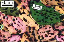

Sea ice growth models for predicting the ice distribution and extent are also valuable for shipping concerns. An ice growth model can be combined with remote sensing measurements in an assimilation model as a means of generating more accurate ice charts.
Overview
Several formation mechanisms of sea ice have been identified. At its earliest stages, sea ice consists of elongated, randomly oriented crystals. This is called frazil and mixed with water in the unconsolidated state is known as grease ice. If wave and wind conditions are calm, these crystals will consolidate at the surface and by selective pressure, begin to grow preferentially in the downward direction, forming nilas. In more turbulent conditions, the frazil will consolidate by mechanical action to form pancake ice, which has a more random structure [1] [2] Another common formation mechanism, especially in the Antarctic where precipitation over sea ice is high, is from snow deposition: on thin ice, the snow will weigh down the ice enough to cause flooding. Subsequent freezing will form ice with a much more granular structure. [3] [4] [5]
One of the more interesting processes to occur within consolidated ice packs is changes in the saline content. As the ice freezes, most of the salt content gets rejected and forms highly saline brine inclusions between the crystals. With decreasing temperatures in the ice sheet, the size of the brine pockets decreases while the salt content goes up. Since ice is less dense than water, increasing pressure causes some of the brine to be ejected from both the top and bottom, producing the characteristic ‘C’-shaped salinity profile of first year ice. [6] Brine will also drain through vertical channels, particularly in the melt season. Thus multi-year ice will tend to have both lower salinity and lower density than first-year ice [2] [7]
Vertical growth
The downward growth of consolidated ice in calm conditions is determined by the rate of heat transfer, Q*, at the ice-water interface. If we assume that the ice is in thermal equilibrium both with itself and its surroundings and that the weather conditions are known, then we can determine Q* by solving the following equation:
for Ts, the surface temperature. The water temperature, Tw, is assumed to be at or near freezing, while the ice thickness, h, is assumed to be known and we can approximate the thermal conductivity, k, as an average over the layers (which have different salinities) or simply use the value for pure ice. The net heat flux is a total over four components:
which are latent, sensible, longwave and shortwave fluxes, respectively. For a description of the approximate parameterizations, see determining surface flux under sea ice thickness. The equation can be solved using a numerical root-finding algorithm such as bisection: the functional dependencies on surface temperature are given, with e being the equilibrium vapor pressure.
While Cox and Weeks [8] assume thermal equilibrium, Tonboe [9] uses a more complex thermodynamic model based on numerical solution of the heat equation. This would be appropriate when the ice is thick or the weather conditions are changing rapidly.
The rate of ice growth can be calculated from heat flux by the following equation:
where L is the latent heat of fusion for water and is the density of ice. The growth rate in turn determines the saline content of the newly frozen ice. Empirical equations for determining the initial brine entrapment in sea ice have been derived by Cox and Weeks[8] and Nakawo and Sinha [10] and take the form:
where S is ice salinity, S0 is the salinity of the parent water and f is an empirical function of ice growth rate, e.g.:
where g is in cm/s.[10]
Salt content
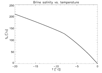
Brine entrapped in sea ice will always be at or near freezing since any departure will either cause some of the water in the brine to freeze, or melt some of the surrounding ice. Thus, brine salinity is variable and can be determined based strictly on temperature—see freezing point depression. References[2][9] and [11] contain empirical formulas relating sea ice temperature to brine salinity.
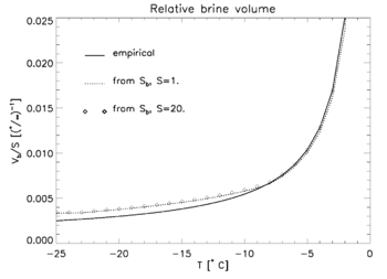
The relative brine volume, Vb, is defined as the fraction of brine relative to the total volume. It too is highly variable, however its value is more difficult to determine since changes in temperature may cause some of the brine to be ejected or move within the layers, particularly in new ice. Writing equations relating the salt content of the brine, the total salt content, the brine volume, the density of the brine and the density of the ice and solving for brine volume produces the following relation:
where S is sea ice salinity, Sb is brine salinity, is the density of the ice and is brine density. Compare with this empirical formula from Ulaby et al.:[11]
where T is ice temperature in degrees Celsius and S is ice salinity in parts per thousand.
In new ice, the amount of brine ejected as the ice cools can be determined by assuming that the total volume stays constant and subtracting the volume increase from the brine volume. Note that this is only applicable to newly formed ice: any warming will tend to generate air pockets as the brine volume will increase more slowly than the ice volume decreases, again due to the density difference. Cox and Weeks[8] provide the following formula determining the ratio of total ice salinity between temperatures, T1 and T2 where T2 < T1:
where c=0.8 kg m−3 is a constant. As the ice goes through constant warming and cooling cycles, it becomes progressively more porous through ejection of the brine and drainage through the resulting channels.
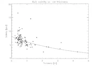
The figure above shows a scatter plot of salinity versus ice thickness for ice cores taken from the Weddell Sea, Antarctica, with an exponential fit of the form, , overlaid, where h is ice thickness and a and b are constants.
Horizontal motion
The horizontal motion of sea ice is quite difficult to model because ice is a non-Newtonian fluid. Sea ice will deform primarily at fracture points which in turn will form at the points of greatest stress and lowest strength, or where the ratio between the two is a maximum. Ice thickness, salinity and porosity will all affect the strength of the ice. The motion of the ice is driven primarily by ocean currents, though to a lesser extent by wind. Note that stresses will not be in the direction of the winds or currents, but rather will be shifted by coriolis effects—see, for instance, Ekman spiral.
References
- G. Maykut; T. Grenfell & W. Weeks (1992). "On estimating spatial and temporal variations in the properties of ice in the polar oceans". Journal of Marine Systems. 3 (1–2): 41–72. Bibcode:1992JMS.....3...41M. doi:10.1016/0924-7963(92)90030-C.
- W. B. Tucker; D. K. Prerovich; A. J. Gow; W. F. Weeks; M. R. Drinkwater (eds.). Microwave Remote Sensing of Sea Ice. American Geophysical Union.
- Ehn, Jens K.; Hwang, Byong Jun; Galley, Ryan; Barber, David G. (2007-05-01). "Investigations of newly formed sea ice in the Cape Bathurst polynya: 1. Structural, physical, and optical properties". Journal of Geophysical Research. 112 (C5): C05002. Bibcode:2007JGRC..112.5002E. doi:10.1029/2006JC003702. ISSN 0148-0227.
- T. Maksym & T. Markus (2008). "Antarctic sea ice thickness and snow-to-ice conversion from atmospheric reanalysis and passive microwave snow depth". Journal of Geophysical Research. 113 (C02S12). Bibcode:2008JGRC..11302S12M. doi:10.1029/2006JC004085.
- S. Tang; D. Qin; J. Ren; J. Kang & Z. Li (2007). "Structure, salinity and isotopic composition of multi-year landfast sea ice in Nella Fjord, Antarctica". Cold Regions Science and Technology. 49 (2): 170–177. doi:10.1016/j.coldregions.2007.03.005.
- Hajo Eicken (1992). "Salinity Profiles of Antarctic Sea ice: Field Data and Model Results". Journal of Geophysical Research. 97 (C10): 15545–15557. Bibcode:1992JGR....9715545E. doi:10.1029/92JC01588.
- M. Vancoppenolle; C. M. Bitz; T. Fichefet (2007). "Summer landfast sea ice desalination at Point Barrow, Alaska: Modeling and observations". Journal of Geophysical Research. 112 (C04022): C04022. Bibcode:2007JGRC..112.4022V. doi:10.1029/2006JC003493.
- G. Cox & W. Weeks (1988). "Numerical simulations of the profile properties of undeformed first-year sea ice during the growth season". Journal of Geophysical Research. 93 (C10): 12449–12460. Bibcode:1988JGR....9312449C. doi:10.1029/JC093iC10p12449.
- G. Heygster, S. Hendricks, L. Kaleschke, N. Maass, P. Mills, D. Stammer, R. T. Tonboe and C. Haas (2009). L-Band Radiometry for Sea-Ice Applications (Technical report). Institute of Environmental Physics, University of Bremen. ESA/ESTEC Contract N. 21130/08/NL/EL.CS1 maint: multiple names: authors list (link)
- M. Nakawo & N. K. Sinha (1981). "Growth rate and salinity profile of first-year sea ice in the high Arctic". Journal of Glaciology. 27 (96): 315–330. Bibcode:1981JGlac..27..315N. doi:10.1017/S0022143000015409.
- F. T. Ulaby; R. K. Moore; A. K. Fung, eds. (1986). Microwave Remote Sensing, Active and Passive. London, England: Addison Wesley.