Sting (fixture)
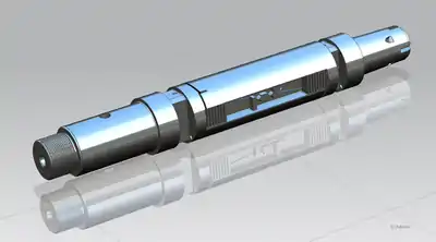
In experimental fluid mechanics, a sting is a test fixture on which models are mounted for testing, e.g. in a wind tunnel. A sting is usually a long shaft attaching to the downstream end of the model so that it does not much disturb the flow over the model. The rear end of a sting usually has a conical fairing blending into the (wind tunnel) model support structure.


.png.webp)
For minimum aerodynamic interference a sting should be as long as possible and have as small a diameter as possible, within the structural safety limits. Critical length of a sting (beyond which its influence on the flow around the model is small) is mostly dependent on Reynolds number. If the flow at the rear end of a model (model base) is laminar, the critical sting length can be as much as 12-15 base diameters.[1] If the flow at model base is turbulent, critical sting length reduces to 3-5 model base diameters. Source [1] also suggests a sting diameter of no more than about 30% of model base diameter. However, this may not be possible in wind tunnels with high dynamic pressures because large aerodynamic loads would cause unacceptably large deflections and/or stresses in the sting. Shorter stings of larger relative diameters must be used in such cases. A good rule-of-thumb is that, for acceptably low and test-conditions-independent aerodynamic interference in a high-Reynolds-number, high-dynamic-pressure wind tunnel, a sting should have a diameter "d" not larger than 30% to 50% of model base diameter "D" and should have a length "L" of at least three model base diameters, e.g. as specified for the AGARD-C calibration model[2]), see figure.
If the test object (model) is to be placed at high angles of attack relative to the airstream (i.e. at an attitude beyond the operating range of the model support mechanism), a bent sting can be used, see figure. Bent stings usually produce higher aerodynamic interference than straight stings. If the test object (model) has a "boattail" rear end without a well-defined base through which a sting shaft can enter the model, a so-called Z-sting can be used, having a form reminiscent of the Latin letter "Z". The part of the sting entering the model is a thin aerodynamically shaped blade so as to minimize disturbance of the flow; see figure.
Stings often attach, at the front end, to internal wind tunnel balances to measure the forces on the model. Therefore, most stings have a central bore through which the cables from a balance or other in-model instrumentation can be conducted without exposure to the airflow.
When a model is mounted on a wind tunnel balance attached to a sting, care must be taken that no parts of the model touch the sting during a wind tunnel test; the only support of the model must be through the balance.

See also
References
- A.Pope, "Wind Tunnel Calibration Techniques", AGARDograph 54, AGARD, 1961
- Wind Tunnel Calibration Models, AGARD Specification 2, AGARD, 1958