Zero-ohm link
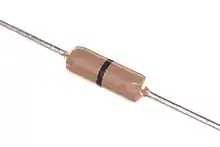
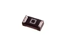
A zero-ohm link or zero-ohm resistor is a wire link packaged in the same physical package format as a resistor. It is used to connect traces on a printed circuit board. This format allows it to be placed on the circuit board using the same automated equipment used to place other resistors, instead of requiring a separate machine to install a jumper or other wire.[1] Zero-ohm resistors may be packaged like cylindrical resistors, or like surface-mount resistors.


One use is to allow traces on the same side of a PCB to cross: one trace has a zero-ohm resistor while the second trace runs in between the leads of the resistor, avoiding contact with the first trace.
The resistance is only approximately zero; only a maximum (typically 10–50 mΩ) is specified.[2] A percentage tolerance would not make sense, as it would be specified as a percentage of the ideal value of zero ohms (which would always be zero), so it is not specified.[3]
An axial-lead through-hole zero-ohm resistor is generally marked with a single black band,[4] the symbol for "0" in the resistor color code. Surface-mount resistors are generally marked with a single "0" or "000".
Design considerations
In practice, zero-ohm resistors can be useful as configuration jumpers, but caution is exercised for PCB designs which may use zero-ohm resistors to select between options which require larger trace currents in the design. For these situations, it is better design practice to specify a low-ohm resistance, such as a 0.001-ohm to 0.003-ohm resistor, rather than the generic "zero-ohm" resistor in which the actual resistance may be higher, and tolerance is not given. The low-ohm resistors are easily obtained with 5% or 1% tolerances on a maximum specified resistance and can be safely utilized to pass much higher currents.
For example, a surface-mounted 0805 size resistor of 0.003 ohms, rated at 0.5 watts can, in theory, safely pass up to 12.9 amperes of current. In practice, when approaching the power limit for a given package, it is good practice to either use an even lower-ohm product (more power-efficient but more expensive) or go up one package size larger (same power efficiency but cost may be kept lower). The "cost" associated with taking up more board space for the larger package may also be a consideration. In this example, for 12 amperes to pass through the jumper, a lower resistance or a bigger surface-mount package (such as a 1206) are usually specified. In contrast, a "worst-case zero-ohm" real-world jumper with 0.05-ohm impedance in a similar 0805 package could only pass 3.1 amperes maximum. The use of specific tolerance resistances is a much safer design practice for higher currents than the "zero-ohm" option, although the bill-of-materials cost can be higher for low-ohm devices.
See also
References
- Blackwell, Glenn R.; Hollomon, James K. (2006). Surface-mount technology for PC boards (2nd ed.). Australia: Thomson Delmar Learning. p. 88. ISBN 978-1-4180-0011-0.
- Archambeault, Bruce R.; Drewniak, James (2002). PCB Design for Real-World EMI Control. Springer. p. 168. ISBN 978-1-4020-7130-0.
- Vishay Intertechnology (27 May 2020). "D/CRCW e3 Standard Thick Film Chip Resistors" (PDF). Mouser Electronics. p. 2. Retrieved 3 February 2020.
Type D10/CRCW0402 e3 / TCR Jumper, Imax. = 1.5 A / tolerance ≤ 20 mOhms
- Paynter, Robert T.; Boydell, Toby (2008). Electronics Technology Fundamentals: Conventional Flow Version (3rd ed.). Prentice Hall. p. 50. ISBN 978-0-13-504874-0.