ANSI/TIA-568
ANSI/TIA-568 is a telecommunication standard, entitled Commercial Building Telecommunications Cabling Standard, by the Telecommunications Industry Association (TIA), a body accredited by the American National Standards Institute (ANSI). The standards address commercial building cabling for telecommunications products and services.
As of 2017, the revision status of the standard is ANSI/TIA-568-D, published December 2015, which replaced TIA/EIA-568-C of 2009, after revision B of 2001, revision A of 1995, and the initial issue of 1991, which are now obsolete.[1][2]
Perhaps the best known features of ANSI/TIA-568 are the pin and pair assignments for eight-conductor 100-ohm balanced twisted pair cabling. These assignments are named T568A and T568B.
History
ANSI/TIA-568 was developed through the efforts of more than 60 contributing organizations including manufacturers, end-users, and consultants. Work on the standard began with the Electronic Industries Alliance (EIA), to define standards for telecommunications cabling systems. EIA agreed to develop a set of standards, and formed the TR-42 committee,[3] with nine subcommittees to perform the work. The work continues to be maintained by TR-42 within the TIA. EIA no longer exists, hence EIA has been removed from the name.
The first version of the standard, TIA/EIA-568, was released in 1991. The standard was updated to revision A in 1995. The demands placed upon commercial wiring systems increased dramatically over this period due to the adoption of personal computers and data communication networks and advances in those technologies. The development of high-performance twisted pair cabling and the popularization of fiber optic cables also drove significant change in the standards. These changes were first released in a revision C in 2009 which has subsequently been replaced by revision D (named ANSI/TIA-568-D).[4]
Goals
ANSI/TIA-568 defines structured cabling system standards for commercial buildings, and between buildings in campus environments. The bulk of the standards define cabling types, distances, connectors, cable system architectures, cable termination standards and performance characteristics, cable installation requirements and methods of testing installed cable. The main standard, ANSI/TIA-568.0-D defines general requirements, while ANSI/TIA-568-C.2 focuses on components of balanced twisted-pair cable systems. ANSI/TIA-568.3-D addresses components of fiber optic cable systems, and ANSI/TIA-568-C.4, addressed coaxial cabling components.[5]
The intent of these standards is to provide recommended practices for the design and installation of cabling systems that will support a wide variety of existing and future services. Developers hope the standards will provide a lifespan for commercial cabling systems in excess of ten years. This effort has been largely successful, as evidenced by the definition of Category 5 cabling in 1991, a cabling standard that (mostly) satisfied cabling requirements for 1000BASE-T, released in 1999. Thus, the standardization process can reasonably be said to have provided at least a nine-year lifespan for premises cabling, and arguably a longer one.
All these documents accompany related standards that define commercial pathways and spaces (TIA-569-C-1, February 2013), residential cabling (ANSI/TIA-570-C, August 2012), administration standards (ANSI/TIA-606-B, December 2015), grounding and bonding (TIA-607-C, November 2015), and outside plant cabling (TIA-758-B, April 2012).
Cable categories
The standard defines categories of shielded and unshielded twisted pair cable systems, with different levels of performance in signal bandwidth, insertion loss, and cross-talk. Generally increasing category numbers correspond with a cable system suitable for higher rates of data transmission. Category 3 cable was suitable for telephone circuits and data rates up to 16 million bits per second. Category 5 cable, with more restrictions on attenuation and cross talk, has a bandwidth of 100 MHz.[6] The 1995 edition of the standard defined Categories 3, 4, and 5. Categories 1 and 2 were excluded from the standard since these categories were only used for voice circuits, not for data.[7] The current revision includes Category 5e (100 MHz), 6 (250 MHz), 6A (500 MHz), and 8 (2,000 MHz). Categories 7 and 7A were not officially recognized by TIA and were generally only used outside the United States. Category 8 was published with ANSI/TIA‑568‑C.2‑1 (June 2016) [8] to meet the performance specification intended by Category 7.
Structured cable system topologies
ANSI/TIA-568-D defines a hierarchical cable system architecture, in which a main cross-connect (MCC) is connected via a star topology across backbone cabling to intermediate cross-connects (ICC) and horizontal cross-connects (HCC). Telecommunications design traditions utilized a similar topology. Many people refer to cross-connects by their telecommunications names: "distribution frames" (with the various hierarchies called MDFs, IDFs and wiring closets). Backbone cabling is also used to interconnect entrance facilities (such as telco demarcation points) to the main cross-connect.
Horizontal cross-connects provide a point for the consolidation of all horizontal cabling, which extends in a star topology to individual work areas such as cubicles and offices. Under TIA/EIA-568-B, maximum allowable horizontal cable distance is 90 m of installed cabling, whether fibre or twisted-pair, with 100 m of maximum total length including patch cords. No patch cord should be longer than 5 m. Optional consolidation points are allowable in horizontal cables, often appropriate for open-plan office layouts where consolidation points or media converters may connect cables to several desks or via partitions.
At the work area, equipment is connected by patch cords to horizontal cabling terminated at jackpoints.
TIA/EIA-568 also defines characteristics and cabling requirements for entrance facilities, equipment rooms and telecommunications rooms.
T568A and T568B termination
Perhaps the widest known and most discussed feature of ANSI/TIA-568 is the definition of the pin-to-pair assignments, or pinout, between the pins in a connector (a plug or a socket) and the wires in a cable. Pinouts are important because cables do not function if the pinouts at their two ends aren't correctly matched.
The standard specifies how to connect eight-conductor 100-ohm balanced twisted-pair cabling, such as Category 5 cable, to 8P8C modular connectors (often incorrectly called RJ45 connectors). The standard defines two alternative pinouts: T568A and T568B.
ANSI/TIA-568 recommends the T568A pinout for horizontal cables. This pinout's advantage is that it is compatible with the 1-pair and 2-pair Universal Service Order Codes (USOC) pinouts. The U.S. Government requires it in federal contracts. The standard also allows the T568B pinout, as an alternative, "if necessary to accommodate certain 8-pin cabling systems". This pinout matches the older AT&T 258A (Systimax) pinout. In the 1990s, when the original TIA/EIA-568 was published, T568A had the most widely installed UTP cabling infrastructure. Many organizations still use T568B out of inertia.
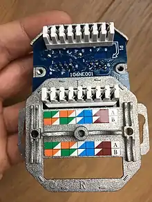
The colors of the wire pairs in the cable, in order, are: blue (for pair 1), orange, green, and brown (for pair 4). Each pair consists of one conductor of solid color and a second conductor which is white with a stripe of the other color. The difference between the T568A and T568B pinouts is that the orange and green wire pairs are exchanged.
Wiring
See modular connector for numbering of the pins.[9]
| Pin | T568A pair | T568B pair | 10BASE-T 100BASE-TX[10] | 1000BASE-T signal ID[11] | Wire | T568A color | T568B color | Pins on plug face |
|---|---|---|---|---|---|---|---|---|
| 1 | 3 | 2 | TX+ | DA+ | tip | white/green stripe | white/orange stripe |  |
| 2 | TX− | DA− | ring | green solid | orange solid | |||
| 3 | 2 | 3 | RX+ | DB+ | tip | white/orange stripe | white/green stripe | |
| 4 | 1 | 1 | not used | DC+ | ring | blue solid | blue solid | |
| 5 | not used | DC− | tip | white/blue stripe | white/blue stripe | |||
| 6 | 2 | 3 | RX− | DB− | ring | orange solid | green solid | |
| 7 | 4 | 4 | not used | DD+ | tip | white/brown stripe | white/brown stripe | |
| 8 | not used | DD− | ring | brown solid | brown solid |
Note that the only difference between T568A and T568B is that pairs 2 and 3 (orange and green respectively) are swapped. Both configurations wire the pins "straight through", i.e., pins 1 through 8 on one end are connected to pins 1 through 8 on the other end.[12] Also, the same sets of pins connect to the opposite ends that are paired in both configurations: pins 1 and 2 form a pair, as do 3 and 6, 4 and 5, and 7 and 8. One can use cables wired according to either configuration in the same installation without significant problem, as long as the connections are the same on both ends.
A cable terminated according to T568A on one end and T568B on the other is, incidentally, effectively a crossover cable when used with the earlier twisted-pair Ethernet standards that use only two of the pairs, because the pairs used happen to be pairs 2 and 3, the same pairs on which T568A and T568B differ. (Since half of its pairs cross over and the other half do not, such a cable is invalid in general and fails for any Ethernet standard that uses more than the two pairs. A proper crossover cable also swaps pairs 1 and 4.) Crossover cables are occasionally needed for 10BASE-T and 100BASE-TX Ethernet.
Swapping two wires between different pairs causes crosstalk, defeating one of the purposes of twisting wires in pairs.[13]
Use for T1 connectivity
In Digital Signal 1 (T1) service, the pairs 1 and 3 (T568A) are used, and the USOC-8 jack is wired according to the RJ-48C specification. The termination jack is often wired according to the RJ-48X specification, which provides for a transmit-to-receive loopback when the plug is withdrawn.
Vendor cables are often wired with tip and ring reversed—i.e. pins 1 and 2 reversed, or pins 4 and 5 reversed. This has no effect on the quality of the T1 signal, which is fully differential and uses the alternate mark inversion (AMI) signaling scheme.
Backward compatibility
Because pair 1 connects to the center pins (4 and 5) of the 8P8C connector in both T568A and T568B, both standards are compatible with the first line of RJ11, RJ14, RJ25, and RJ61 connectors that all have the first pair in the center pins of these connectors.
If the second line of an RJ14, RJ25 or RJ61 plug is used, it connects to pair 2 (orange/white) of jacks wired to T568A but to pair 3 (green/white) in jacks wired to T568B. This makes T568B potentially confusing in telephone applications.
Because of different pin pairings, the RJ25 and RJ61 plugs cannot pick up lines 3 or 4 from either T568A or T568B without splitting pairs. This would most likely result in unacceptable levels of hum, crosstalk and noise.
Theory
The original idea in wiring modular connectors, as seen in the registered jacks, was that the first pair would go in the center positions, the next pair on the next-innerermost ones, and so on. Also, signal shielding would be optimized by alternating the "live" and "earthy" pins of each pair. The terminations diverge slightly from this concept because on the eight-position connector the resulting arrangement of conductors would separate the outermost pair impairing balanced line performance too much to meet the electrical requirements of high-speed LAN protocols.
Standards
- ANSI/TIA-568.0-D, Generic Telecommunications Cabling for Customer Premises, Ed. D, 09-2015
- ANSI/TIA-568.1-D, Commercial Building Telecommunications Cabling Standard, Ed. D, 09-2015
- ANSI/TIA-568-C.2, Balanced Twisted-Pair Telecommunication Cabling and Components Standard, Ed. C, Err. 04-2014
- ANSI/TIA-568.3-D, Optical Fiber Cabling And Components Standard, Ed. D, 10-2016
- ANSI/TIA-568-C.4, Broadband Coaxial Cabling and Components Standard, Ed. C, 07-2011
See also
- ISO/IEC 11801, similar standards for network cables
References
- Andrew Oliviero, Bill Woodward "Cabling: The Complete Guide to Copper and Fiber-Optic Networking", John Wiley & Sons, 2009, ISBN 0470550058 page 68
- "Standards and Technology Annual Report" (PDF). TIA. Retrieved 2014-04-14.
- "TR-42 - Telecommunications Cabling Systems". TIA. Retrieved 2014-04-14.
- "TIA-568 Set : Commercial Building Telecommunications Cabling Standards Set".
- "TIA Publishes New Cabling Standards Designed to Improve Efficiency for Designers, Installers and End Users". TIA. 2009-03-12. Archived from the original on 2011-08-17.
- William Stallings Knowing UTP wiring basics can boost local net performance, Network World 9 July 1996, page 29
- Charles E. Spurgeon, Ethernet:The Definitive Guide, (O'Reilly Media, Inc., 2000) ISBN 1565926609 page 212
- https://blog.siemon.com/standards/answers-to-your-top-category-8-cabling-questions
- "Connector Pin Assignments". Cisco. Retrieved 2014-04-14.
- IEEE 802.3 Table 25-2
- IEEE 802.3 Table 40-12
- "RJ45 Pinout".
- "LAN Wiring & Pinouts".
Sources
- "National Communications System Federal Telecommunications Recommendation 1090-1997". Retrieved 2014-04-14.
External links
| Wikimedia Commons has media related to Computer network. |
