Concrete sleeper
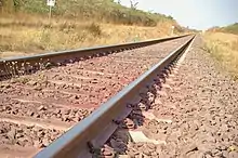
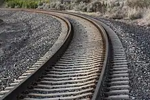
A concrete sleeper (British English) or concrete tie (American English) is a type of railway sleeper or railroad tie made out of steel reinforced concrete.


Concrete sleepers are less elastic, and consequently noisier than wooden sleepers as trains pass over them.
History
In 1877, Joseph Monier, a French gardener, suggested that concrete reinforced with steel could be used for making sleepers for railway track. Monier designed a sleeper and obtained a patent for it, but it was not successful.
Concrete sleepers were first used on the Alford and Sutton Tramway in 1884. Their first use on a main line railway was by the Reading Company in America in 1896, as recorded by AREA Proceedings at the time. Designs were further developed and the railways of Austria and Italy used the first concrete sleepers around the turn of the 20th century. This was closely followed by other European railways.
Major progress was not achieved until World War II, when the timbers used for sleepers were scarce due to competition from other uses, such as mines.[1] Following research carried out on French and other European railways, the modern pre-stressed concrete sleeper was developed. Heavier rail sections and long welded rails were also being installed, requiring higher-quality sleepers. These conditions spurred the development of concrete sleepers in France, Germany and Britain, where the technology was perfected.
The 1 ft 11 1⁄2 in (597 mm) gauge Lynton and Barnstaple Railway (1898 to 1935) in North Devon, experimented with concrete sleepers at a number of locations along the line. As the sleepers were cast to gauge, they were of little use outside the station areas on this very curvaceous line where gauge slackening was commonly required. They were also noisy and lacked the elasticity of wooden sleepers creating a very rigid road.[2] Some of those concrete sleepers can now be seen on display at Woody Bay Station.[3]
Interest in concrete railway sleepers increased after World War II following advances in the design, quality and production of pre-stressed concrete.
Chaired bullhead concrete sleepers have been around since at least the 1940s; the Great Western using a two-holed chair, thus saving both scarce wartime timber and steel fixing bolts.[4] This design was used by the government-run railways during World War II and in particular immediately prior to D-Day when timber was scarce and track extension or replacement was urgently required. Gravesend West Street station was thus relaid in 1944 to enable the huge increase in freight to be handled.[5]
Types

Concrete sleepers can be one piece of uniform or variable dimensions. They can also consist of two separate blocks connected by a steel tie rod. Again, the Great Western Railway during World War Two produced chaired "pot" type sleepers — two concrete pods connected by steel bars — for use on sidings and some loops but these monoblock pot sleepers did not carry a gauge-tie at every position, such usually being placed every 3 or 4 pots or successively at rail joints. Such an example was recorded in a siding at Talyllyn East Junction and at Rock Siding, Talybont-on Usk, on the former Brecon & Merthyr Railway in September 1963. Until quite recently, examples were to be seen at Dovey Junction on the Cambrian Coast and others may still exist elsewhere.[6]
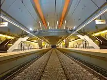
Exceptionally, the concrete can be poured as two separate longitudinal slabs, as has been used in Namibia. Slab track consists of a continuous concrete roadbed without division into separate sleepers, and these are most often used in tunnels. British Rail experimented with slabs during the late 1960s and laid several miles alongside the main running lines north of Derby.
Under sleeper pads
Concrete sleepers lack the elasticity of wooden sleepers and, therefore, ballast tracks with concrete sleepers usually have a much quicker degradation of the ballast when loaded. This is especially true in curves, turnouts and switches. To reduce the wear on the ballast, and in some cases offer vibration isolation, pads are fitted to the base of the sleeper. The pads are usually manufactured of polyurethane foams with a stiffness tailored to meet the elasticity requirements of the track.
To reduce the wear of the ballast, the best material to use is a very stiff semi-plastic polyurethane foam that mimics the plastic behaviour of wooden sleepers; the ballast stones are pressed into the surface of the sleeper, increasing contact area. Typically, these pads are 7–10 mm thick.
In order to achieve vibration isolation as well, the elastic layer needs to be softer, and in many cases thicker. A vibration isolation of 5-12 dB can be achieved, but the results will depend on many factors, such as axle load, velocity, subsoil stiffness, ballast thickness, ballast quality and more. Therefore, it is very difficult to predict the results exactly.
Advantages and disadvantages
Advantages

Advantages include: They do not rot like timber sleepers, are fire proof, their extra weight makes track more stable (particularly with changes in temperature), they can withstand fire hazards better than wooden sleepers, they give more retentivity to the track, they have a longer life than wooden sleepers, and they need less maintenance, resulting in lower ongoing costs and fewer track closures. Additionally, concrete sleepers are not soaked in creosote like most wooden sleepers (used mainly in Europe), therefore they are environmentally friendlier.
Disadvantages
Disadvantages include: When trains derail and the wheels hit the sleepers, timber sleepers tend to absorb the blow and remain intact, while concrete sleepers tend to shatter and have to be replaced. Initial costs are greater, and they are unsuitable for change of gauge, unless this is already taken into account. Concrete sleepers are up to 300 pounds (136.1 kg) heavier than their wooden counterparts. As a result, larger sized ballast is required to both support and hold in place the sleepers on the roadbed. Additionally, they do not absorb as much vibration from passing trains as wooden sleepers do. This can cause degradation of the sleepers themselves ranging from small cracks to complete failure over time. This problem is most prevalent when the sleepers are located next to joints in the rails. For this reason, railroads which used concrete sleepers for plain line avoided them on turnouts and interlockings; however, modern designs allow use of concrete bearers for turnouts and they have become standard for switch renewals on many railways. Another potential fault is lateral rigidity which may cause cumulative metal fatigue, particularly on reverse curves where the stresses are accentuated by the abrupt change of lateral forces. This in turn may be the cause of gauge corner cracking in the rails themselves as well as the steel sleeper reinforcement.
German railways have experienced cracking of their sleepers on high speed lines and have had to replace many thousands of them after only a short life; however, this was found to be due to use of inappropriate aggregate in the concrete mix.[7] Damaged concrete sleepers cannot be repaired. Old concrete sleepers can be used for things like retaining walls, else they might be crushed to recycle gravel and the steel reinforcing.[8]
Special sleepers may be necessary on extremely sharp curves, such as the new triangle at Newmarket, New Zealand on the 1,067 mm (3 ft 6 in) gauge of radius 95 m (312 ft). Here the sleepers are extra heavy, about 250 kg, and may include gauge widening with transitional gauge widening.[9]
Concrete sleepers for turnouts must be individually custom designed for the location. They are much longer than normal sleepers, have gaps for switch motors, and are generally made by a small number of specialist manufacturers. If a turnout is needed in a hurry, it may be made with timber sleepers which can simply be drilled to suit.
Standards
USC, the international railway union, has issued a standard (#710) for concrete sleepers.
In other countries, such as Malaysia and Singapore, various standards are used, such as Australian Standards, AS 1085.14:2012 (Railway Track Material - Prestressed Concrete Sleepers), or EN 13230-4:2016 (Railway applications - Track Concrete sleepers and bearers, Part 4: Prestressed bearers for switches and crossings). UIC 713R leaflet is also used as supplementary reference due to Part 6 of EN 13230, is still in draft stage, i.e. pr EN 13230-6:2016. 122333
Manufacture, transport, and installation
.jpg.webp)
Concrete sleepers are made upside down in moulds, several sleepers long. Pandrol clip bases or other fittings are inserted into the moulds. Pre-stressed steel reinforcing bars are installed in these moulds, and then the concrete is poured. It takes several days for the concrete to cure, after which the sleepers are removed from the moulds and cut into individual sleepers. The bottom of the mould is marked with the logo of the manufacturer and a date stamp.
Occasionally, sleepers are made with conduits for track circuit wiring, or extra fixtures for guard rails. Sleepers can be made using a Long Line method or a Short Line method; each method has its advantages and disadvantages.[10]
Multiple companies manufacture sleepers around the world. They are transported to the work site in small stacks, with pieces of lumber separating the layers of sleepers. They are then laid using manual methods or using various sleeper laying machines.
Regulation
United States
On 8 November 2011, the United States Federal Railroad Administration (FRA) put into effect new regulations on concrete sleepers, with notices published by the FRA in the 1 April – 9 September 2011 U.S. Federal Register. The FRA notices said that the need for the new rules was shown by the derailment of an Amtrak train near Home Valley, Washington on 3 April 2005, which, according to the U.S. National Transportation Safety Board, was caused in part by excessive concrete tie abrasion. To be counted as a good tie under FRA regulation 213.109(d)(4), concrete ties shall not be deteriorated or abraded under the rail to a depth of one-half inch or more. Limits on other types of concrete tie deterioration are also given.
See also
- Sleeper
- Ladder track - longitudinal sleepers
- Tubular Modular Track
- Track ballast
- AS [11]
References
- Hay 1982, p. 470
- Steve Phillips The Lynton & Barnstaple Measured & Drawn
- http://www.lynton-rail.co.uk
- British Standard 986
- Family knowledge
- Railway Gazette May 1944
- ":: View topic - German track in big trouble". Archived from the original on 7 October 2011. Retrieved 31 May 2008.
- concrete sleeper crusher - YouTube
- Railway Gazette International March, 2012, page 23
- http://www.austrak.com/content/production-technology/long-line-vs-short-line/
- http://infostore.saiglobal.com/store/details.aspx?ProductID=1604811
External links
![]() Media related to Concrete sleeper at Wikimedia Commons
Media related to Concrete sleeper at Wikimedia Commons