Corona ring
A corona ring, also called an anti-corona ring, is a toroid of conductive material, usually metal, which is attached to a terminal or other irregular hardware piece of high voltage equipment. The role of the corona ring is to distribute the electric field gradient and lower its maximum values below the corona threshold, either preventing corona discharge entirely or transferring its destructive effects from the valuable hardware to the expendable ring. Corona rings are used on very high voltage power transmission insulators and switchgear, and on scientific research apparatus that generates high voltages. A very similar related device, the grading ring, is used around insulators.
Corona discharge
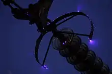
Corona discharge is a leakage of electric current into the air adjacent to high voltage conductors. It is sometimes visible as a dim blue glow in the air next to sharp points on high voltage equipment. The high electric field ionizes the air, making it conductive, allowing current to leak from the conductor into the air in the form of ions. In electric power transmission lines and equipment, corona results in an economically significant waste of power and may deteriorate the hardware from where it originates. In devices such as electrostatic generators, Marx generators, and television sets, the current load caused by corona leakage can reduce the voltage produced by the device, causing it to malfunction. Coronas also produce noxious and corrosive ozone gas, which can cause aging and embrittlement of nearby structures such as insulators, and create a health hazard for workers and local residents. For these reasons corona discharge is considered undesirable in most electrical equipment.
How they work
Corona discharges only occur when the electric field (potential gradient) at the surface of conductors exceeds a critical value, the dielectric strength or disruptive potential gradient of air. It is roughly 30 kilovolts per centimeter, but decreases with atmospheric pressure, so corona is more of a problem at high altitudes. The electric field at a conductor is greatest where the curvature is sharpest, and therefore corona discharge occurs first at sharp points, corners and edges.
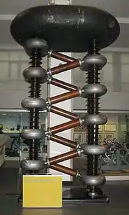
The terminals on very high voltage equipment are frequently designed with large diameter rounded shapes such as balls and toruses called corona caps, to suppress corona formation. Some parts of high voltage circuits have hardware with exposed sharp edges or corners, such as the attachment points where wires or bus bars are connected to insulators; corona caps and rings are usually installed at these points to prevent corona formation.
The corona ring is electrically connected to the high voltage conductor, encircling the points where corona would form. Since the ring is at the same potential as the conductor, the presence of the ring reduces the potential gradient at the surface of the conductor greatly, below the disruptive potential gradient, so corona does not form on the metal points.
Grading rings
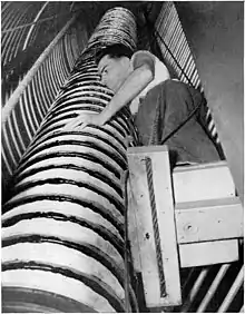
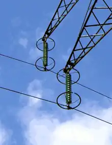
A very similar related device, called a grading ring, is also used on high-voltage equipment. Grading rings are similar to corona rings, but they encircle insulators rather than conductors. Although they may also serve to suppress corona, their main purpose is to reduce the potential gradient along the insulator, preventing premature electrical breakdown.
The potential gradient (electric field) across an insulator is not uniform, but is highest at the end next to the high voltage electrode. If subjected to a high enough voltage, the insulator will break down and become conductive at that end first. Once a section of insulator at the end has electrically broken down and become conductive, the full voltage is applied across the remaining length, so the breakdown will quickly progress from the high voltage end to the other, and a flashover arc will start. Therefore, insulators can stand significantly higher voltages if the potential gradient at the high voltage end is reduced.
The grading ring surrounds the end of the insulator next to the high voltage conductor. It reduces the gradient at the end, resulting in a more even voltage gradient along the insulator, allowing a shorter, cheaper insulator to be used for a given voltage. Grading rings also reduce aging and deterioration of the insulator that can occur at the high voltage end due to the high electric field there.
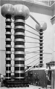
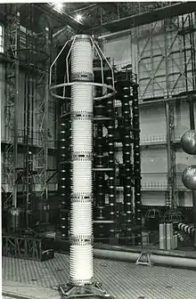
In very high voltage apparatus like Marx generators and particle accelerator tubes, insulating columns often have many metal grading rings spaced evenly along their length. These are linked by a voltage divider chain of high value resistors so there is an equal voltage drop from each ring to the next. This divides the potential difference evenly along the length of the column so there are no high field spots, resulting in the least stress on the insulators.
Uses
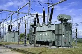
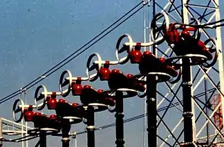
Corona rings are used on extremely high voltage apparatus like Van de Graaff generators, Cockcroft–Walton generators, and particle accelerators, as well as electric power transmission insulators, bushings and switchgear. Manufacturers suggest a corona ring on the line end of the insulator for transmission lines above 230 kV and on both ends for potentials above 500 kV. Corona rings prolong the lifetime of insulator surfaces by suppressing the effects of corona discharge.[1]
Corona rings may also be installed on the insulators of antennas of high-power radio transmitters.[2] However, they increase the capacitance of the insulators.[3]
See also
References
- Electric power generation, transmission, and distribution, Volume 1 By Leonard L. Grigsby, CRC Press, 2007, ISBN 0-8493-9292-6
- The Handbook of antenna design, Volume 2 By Alan W. Rudge, IET, 1983, p. 873, ISBN 0-906048-87-7
- aerials for metre and decimetre wave-lengths, CUP Archive