Antenna (radio)
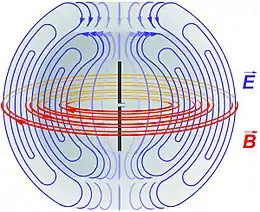
In radio engineering, an antenna or aerial is the interface between radio waves propagating through space and electric currents moving in metal conductors, used with a transmitter or receiver.[1] In transmission, a radio transmitter supplies an electric current to the antenna's terminals, and the antenna radiates the energy from the current as electromagnetic waves (radio waves). In reception, an antenna intercepts some of the power of a radio wave in order to produce an electric current at its terminals, that is applied to a receiver to be amplified. Antennas are essential components of all radio equipment.
An antenna is an array of conductors (elements), electrically connected to the receiver or transmitter. Antennas can be designed to transmit and receive radio waves in all horizontal directions equally (omnidirectional antennas), or preferentially in a particular direction (directional, or high-gain, or “beam” antennas). An antenna may include components not connected to the transmitter, parabolic reflectors, horns, or parasitic elements, which serve to direct the radio waves into a beam or other desired radiation pattern.
The first antennas were built in 1888 by German physicist Heinrich Hertz in his pioneering experiments to prove the existence of waves predicted by the electromagnetic theory of James Clerk Maxwell. Hertz placed dipole antennas at the focal point of parabolic reflectors for both transmitting and receiving.[2] Starting in 1895, Guglielmo Marconi began development of antennas practical for long-distance, wireless telegraphy, for which he received a Nobel Prize.[3]
Terminology

The words antenna and aerial are used interchangeably. Occasionally the equivalent term “aerial” is used to specifically mean an elevated horizontal wire antenna. The origin of the word antenna relative to wireless apparatus is attributed to Italian radio pioneer Guglielmo Marconi. In the summer of 1895, Marconi began testing his wireless system outdoors on his father's estate near Bologna and soon began to experiment with long wire "aerials" suspended from a pole.[3] In Italian a tent pole is known as l'antenna centrale, and the pole with the wire was simply called l'antenna. Until then wireless radiating transmitting and receiving elements were known simply as “terminals”. Because of his prominence, Marconi's use of the word antenna spread among wireless researchers and enthusiasts, and later to the general public.[4][5][6]
Antenna may refer broadly to an entire assembly including support structure, enclosure (if any), etc., in addition to the actual functional components. A receiving antenna may include not only the passive metal receiving elements, but also an integrated preamplifier or mixer, especially at and above microwave frequencies.
Overview
_by_night_under_the_Magellanic_Clouds.jpg.webp)
Antennas are required by any radio receiver or transmitter to couple its electrical connection to the electromagnetic field.[8] Radio waves are electromagnetic waves which carry signals through the air (or through space) at the speed of light with almost no transmission loss.
Antennas can be classified as omnidirectional, radiating energy approximately equally in all directions, or directional, where energy radiates more along one direction than others. (Antennas are reciprocal, so the same effect occurs for reception of radio waves.) A completely uniform omnidirectional antenna is not physically possible. Some antenna types have a uniform radiation pattern in the horizontal plane, but send little energy upward or downward. A "directional" antenna usually is intended to maximize its coupling to the electromagnetic field in the direction of the other station.
A vertical antenna or whip antenna radiates in all directions horizontally, but sends less energy upward or downward. Similarly, a dipole antenna oriented horizontally sends little energy in direction vectors parallel to the conductor; this region is called the antenna null.
The dipole antenna, which is the basis for most antenna designs, is a balanced component, with equal but opposite voltages and currents applied at its two terminals. The vertical antenna is a monopole antenna, not balanced with respect to ground. The ground (or any large conductive surface) plays the role of the second conductor of a dipole. Since monopole antennas rely on a conductive surface, they may be mounted with a ground plane to approximate the effect of being mounted on the Earth's surface.
More complex antennas increase the directivity of the antenna. Additional elements in the antenna structure, which need not be directly connected to the receiver or transmitter, increase its directionality. Antenna "gain" describes the concentration of radiated power into a particular solid angle of space. "Gain" is perhaps an unfortunately chosen term, by comparison with amplifier "gain" which implies a net increase in power. In contrast, for antenna "gain", the power increased in the desired direction is at the expense of power reduced in undesired directions. Unlike amplifiers, antennas are electrically “passive” devices which conserve total power, and there is no increase in total power above that delivered from the power source (the transmitter), only improved distribution of that fixed total.
A phased array consists of two or more simple antennas which are connected together through an electrical network. This often involves a number of parallel dipole antennas with a certain spacing. Depending on the relative phase introduced by the network, the same combination of dipole antennas can operate as a "broadside array" (directional normal to a line connecting the elements) or as an "end-fire array" (directional along the line connecting the elements). Antenna arrays may employ any basic (omnidirectional or weakly directional) antenna type, such as dipole, loop or slot antennas. These elements are often identical.
A log-periodic dipole array consists of a number of dipole elements of different lengths in order to obtain a somewhat directional antenna having an extremely wide bandwidth. The dipole antennas composing it are all considered "active elements" since they are all electrically connected together (and to the transmission line). A Yagi–Uda antenna (or simply "Yagi"), has only one dipole element with an electrical connection; the other parasitic elements interact with the electromagnetic field in order to realize a directional antenna over a narrow bandwidth. There may be a number of so-called "directors" in front of the active element in the direction of propagation, and one or more "reflectors" on the opposite side of the active element.
Greater directionality can be obtained using beam-forming techniques such as a parabolic reflector or a horn. Since high directivity in an antenna depends on it being large compared to the wavelength, narrow beams of this type are more easily achieved at UHF and microwave frequencies.
At low frequencies (such as AM broadcast), arrays of vertical towers are used to achieve directionality[9] and they will occupy large areas of land. For reception, a long Beverage antenna can have significant directivity. For non directional portable use, a short vertical antenna or small loop antenna works well, with the main design challenge being that of impedance matching. With a vertical antenna a loading coil at the base of the antenna may be employed to cancel the reactive component of impedance; small loop antennas are tuned with parallel capacitors for this purpose.
An antenna lead-in is the transmission line, or feed line, which connects the antenna to a transmitter or receiver. The “antenna feed” may refer to all components connecting the antenna to the transmitter or receiver, such as an impedance matching network in addition to the transmission line. In a so-called “aperture antenna”, such as a horn or parabolic dish, the “feed” may also refer to a basic radiating antenna embedded in the entire system of reflecting elements (normally at the focus of the parabolic dish or at the throat of a horn) which could be considered the one active element in that antenna system. A microwave antenna may also be fed directly from a waveguide in place of a (conductive) transmission line.
An antenna counterpoise, or ground plane, is a structure of conductive material which improves or substitutes for the ground. It may be connected to or insulated from the natural ground. In a monopole antenna, this aids in the function of the natural ground, particularly where variations (or limitations) of the characteristics of the natural ground interfere with its proper function. Such a structure is normally connected to the return connection of an unbalanced transmission line such as the shield of a coaxial cable.
An electromagnetic wave refractor in some aperture antennas is a component which due to its shape and position functions to selectively delay or advance portions of the electromagnetic wavefront passing through it. The refractor alters the spatial characteristics of the wave on one side relative to the other side. It can, for instance, bring the wave to a focus or alter the wave front in other ways, generally in order to maximize the directivity of the antenna system. This is the radio equivalent of an optical lens.
An antenna coupling network is a passive network (generally a combination of inductive and capacitive circuit elements) used for impedance matching in between the antenna and the transmitter or receiver. This may be used to improve the standing wave ratio in order to minimize losses in the transmission line and to present the transmitter or receiver with a standard resistive impedance that it expects to see for optimum operation.
Reciprocity
It is a fundamental property of antennas that the electrical characteristics of an antenna described in the next section, such as gain, radiation pattern, impedance, bandwidth, resonant frequency and polarization, are the same whether the antenna is transmitting or receiving.[10][11] For example, the "receiving pattern" (sensitivity as a function of direction) of an antenna when used for reception is identical to the radiation pattern of the antenna when it is driven and functions as a radiator. This is a consequence of the reciprocity theorem of electromagnetics.[11] Therefore, in discussions of antenna properties no distinction is usually made between receiving and transmitting terminology, and the antenna can be viewed as either transmitting or receiving, whichever is more convenient.
A necessary condition for the aforementioned reciprocity property is that the materials in the antenna and transmission medium are linear and reciprocal. Reciprocal (or bilateral) means that the material has the same response to an electric current or magnetic field in one direction, as it has to the field or current in the opposite direction. Most materials used in antennas meet these conditions, but some microwave antennas use high-tech components such as isolators and circulators, made of nonreciprocal materials such as ferrite.[10][11] These can be used to give the antenna a different behavior on receiving than it has on transmitting,[10] which can be useful in applications like radar.
Resonant antennas
The majority of antenna designs are based on the resonance principle. This relies on the behaviour of moving electrons, which reflect off surfaces where the dielectric constant changes, in a fashion similar to the way light reflects when optical properties change. In these designs, the reflective surface is created by the end of a conductor, normally a thin metal wire or rod, which in the simplest case has a feed point at one end where it is connected to a transmission line. The conductor, or element, is aligned with the electrical field of the desired signal, normally meaning it is perpendicular to the line from the antenna to the source (or receiver in the case of a broadcast antenna).[12]
The radio signal's electrical component induces a voltage in the conductor. This causes an electrical current to begin flowing in the direction of the signal's instantaneous field. When the resulting current reaches the end of the conductor, it reflects, which is equivalent to a 180-degree change in phase. If the conductor is 1⁄4 of a wavelength long, current from the feed point will undergo 90 degree phase change by the time it reaches the end of the conductor, reflect through 180 degrees, and then another 90 degrees as it travels back. That means it has undergone a total 360 degree phase change, returning it to the original signal. The current in the element thus adds to the current being created from the source at that instant. This process creates a standing wave in the conductor, with the maximum current at the feed.[13]
The ordinary half-wave dipole is probably the most widely used antenna design. This consists of two 1⁄4 wavelength elements arranged end-to-end, and lying along essentially the same axis (or collinear), each feeding one side of a two-conductor transmission wire. The physical arrangement of the two elements places them 180 degrees out of phase, which means that at any given instant one of the elements is driving current into the transmission line while the other is pulling it out. The monopole antenna is essentially one half of the half-wave dipole, a single 1⁄4 wavelength element with the other side connected to ground or an equivalent ground plane (or counterpoise). Monopoles, which are one-half the size of a dipole, are common for long-wavelength radio signals where a dipole would be impractically large. Another common design is the folded dipole which consists of two (or more) half-wave dipoles placed side-by-side and connected at their ends but only one of which is driven.
The standing wave forms with this desired pattern at the design operating frequency, fo, and antennas are normally designed to be this size. However, feeding that element with 3 f0 (whose wavelength is 1⁄3 that of fo) will also lead to a standing wave pattern. Thus, an antenna element is also resonant when its length is 3⁄4 of a wavelength. This is true for all odd multiples of 1⁄4 wavelength. This allows some flexibility of design in terms of antenna lengths and feed points. Antennas used in such a fashion are known to be harmonically operated.[14] Resonant antennas usually use a linear conductor (or element), or pair of such elements, each of which is about a quarter of the wavelength in length (an odd multiple of quarter wavelengths will also be resonant). Antennas that are required to be small compared to the wavelength sacrifice efficiency and cannot be very directional. Since wavelengths are so small at higher frequencies (UHF, microwaves) trading off performance to obtain a smaller physical size is usually not required.
Current and voltage distribution
The quarter-wave elements imitate a series-resonant electrical element due to the standing wave present along the conductor. At the resonant frequency, the standing wave has a current peak and voltage node (minimum) at the feed. In electrical terms, this means the element has minimum reactance, generating the maximum current for minimum voltage. This is the ideal situation, because it produces the maximum output for the minimum input, producing the highest possible efficiency. Contrary to an ideal (lossless) series-resonant circuit, a finite resistance remains (corresponding to the relatively small voltage at the feed-point) due to the antenna's radiation resistance as well as any actual electrical losses.
Recall that a current will reflect when there are changes in the electrical properties of the material. In order to efficiently transfer the received signal into the transmission line, it is important that the transmission line has the same impedance as its connection point on the antenna, otherwise some of the signal will be reflected backwards into the body of the antenna; likewise part of the transmitter's signal power will be reflected back to transmitter, if there is a change in electrical impedance where the feedline joins the antenna. This leads to the concept of impedance matching, the design of the overall system of antenna and transmission line so the impedance is as close as possible, thereby reducing these losses. Impedance matching is accomplished by a circuit called an antenna tuner or impedance matching network between the transmitter and antenna. The impedance match between the feedline and antenna is measured by a parameter called the standing wave ratio (SWR) on the feedline.
Consider a half-wave dipole designed to work with signals with wavelength 1 m, meaning the antenna would be approximately 50 cm from tip to tip. If the element has a length-to-diameter ratio of 1000, it will have an inherent impedance of about 63 ohms resistive. Using the appropriate transmission wire or balun, we match that resistance to ensure minimum signal reflection. Feeding that antenna with a current of 1 Ampere will require 63 Volts, and the antenna will radiate 63 Watts (ignoring losses) of radio frequency power. Now consider the case when the antenna is fed a signal with a wavelength of 1.25 m; in this case the current induced by the signal would arrive at the antenna's feedpoint out-of-phase with the signal, causing the net current to drop while the voltage remains the same. Electrically this appears to be a very high impedance. The antenna and transmission line no longer have the same impedance, and the signal will be reflected back into the antenna, reducing output. This could be addressed by changing the matching system between the antenna and transmission line, but that solution only works well at the new design frequency.
The end result is that the resonant antenna will efficiently feed a signal into the transmission line only when the source signal's frequency is close to that of the design frequency of the antenna, or one of the resonant multiples. This makes resonant antenna designs inherently narrow-band: Only useful for a small range of frequencies centered around the resonance(s).
Electrically short antennas
It is possible to use simple impedance matching techniques to allow the use of monopole or dipole antennas substantially shorter than the 1⁄4 or 1⁄2 wavelength, respectively, at which they are resonant. As these antennas are made shorter (for a given frequency) their impedance becomes dominated by a series capacitive (negative) reactance; by adding an appropriate size “loading coil” – a series inductance with equal and opposite (positive) reactance – the antenna's capacitive reactance may be cancelled leaving only a pure resistance. Sometimes the resulting (lower) electrical resonant frequency of such a system (antenna plus matching network) is described using the concept of electrical length, so an antenna used at a lower frequency than its resonant frequency is called an electrically short antenna[15]
For example, at 30 MHz (10 m wavelength) a true resonant 1⁄4 wavelength monopole would be almost 2.5 meters long, and using an antenna only 1.5 meters tall would require the addition of a loading coil. Then it may be said that the coil has lengthened the antenna to achieve an electrical length of 2.5 meters. However, the resulting resistive impedance achieved will be quite a bit lower than that of a true 1⁄4 wave (resonant) monopole, often requiring further impedance matching (a transformer) to the desired transmission line. For ever shorter antennas (requiring greater "electrical lengthening") the radiation resistance plummets (approximately according to the square of the antenna length), so that the mismatch due to a net reactance away from the electrical resonance worsens. Or one could as well say that the equivalent resonant circuit of the antenna system has a higher Q factor and thus a reduced bandwidth,[15] which can even become inadequate for the transmitted signal's spectrum. Resistive losses due to the loading coil, relative to the decreased radiation resistance, entail a reduced electrical efficiency, which can be of great concern for a transmitting antenna, but bandwidth is the major factor that sets the size of antennas at 1 MHz and lower frequencies.
Arrays and reflectors
The amount of signal received from a distant transmission source is essentially geometric in nature due to the inverse-square law, and this leads to the concept of effective area. This measures the performance of an antenna by comparing the amount of power it generates to the amount of power in the original signal, measured in terms of the signal's power density in Watts per square metre. A half-wave dipole has an effective area of . If more performance is needed, one cannot simply make the antenna larger. Although this would intercept more energy from the signal, due to the considerations above, it would decrease the output significantly due to it moving away from the resonant length. In roles where higher performance is needed, designers often use multiple elements combined together.

Returning to the basic concept of current flows in a conductor, consider what happens if a half-wave dipole is not connected to a feed point, but instead shorted out. Electrically this forms a single 1⁄2 wavelength element. But the overall current pattern is the same; the current will be zero at the two ends, and reach a maximum in the center. Thus signals near the design frequency will continue to create a standing wave pattern. Any varying electrical current, like the standing wave in the element, will radiate a signal. In this case, aside from resistive losses in the element, the rebroadcast signal will be significantly similar to the original signal in both magnitude and shape. If this element is placed so its signal reaches the main dipole in-phase, it will reinforce the original signal, and increase the current in the dipole. Elements used in this way are known as “passive elements”.
A Yagi-Uda array uses passive elements to greatly increase gain. It is built along a support boom that is pointed toward the signal, and thus sees no induced signal and does not contribute to the antenna's operation. The end closer to the source is referred to as the front. Near the rear is a single active element, typically a half-wave dipole or folded dipole. Passive elements are arranged in front (directors) and behind (reflectors) the active element along the boom. The Yagi has the inherent quality that it becomes increasingly directional, and thus has higher gain, as the number of elements increases. However, this also makes it increasingly sensitive to changes in frequency; if the signal frequency changes, not only does the active element receive less energy directly, but all of the passive elements adding to that signal also decrease their output as well and their signals no longer reach the active element in-phase.
It is also possible to use multiple active elements and combine them together with transmission lines to produce a similar system where the phases add up to reinforce the output. The antenna array and very similar reflective array antenna consist of multiple elements, often half-wave dipoles, spaced out on a plane and wired together with transmission lines with specific phase lengths to produce a single in-phase signal at the output. The log-periodic antenna is a more complex design that uses multiple in-line elements similar in appearance to the Yagi-Uda but using transmission lines between the elements to produce the output.
Reflection of the original signal also occurs when it hits an extended conductive surface, in a fashion similar to a mirror. This effect can also be used to increase signal through the use of a reflector, normally placed behind the active element and spaced so the reflected signal reaches the element in-phase. Generally the reflector will remain highly reflective even if it is not solid; gaps less than 1⁄10 generally have little effect on the outcome. For this reason, reflectors often take the form of wire meshes or rows of passive elements, which makes them lighter and less subject to wind-load effects, of particular importance when mounted at higher elevations with respect to the surrounding structures. The parabolic reflector is perhaps the best known example of a reflector-based antenna, which has an effective area far greater than the active element alone.

Modeling antennas with line equations
The equations governing the flow of current in wire antennas are identical to the telegrapher's equations,[16]:7–10 [17]:232 so antenna segments can be modeled as a two-way, single-conductor transmission lines. The antenna is broken into multiple line segments, each segment having approximately constant primary line parameters, R, L, C, and G, and current dividing at each junction based on impedance.[lower-alpha 1]
At the tip of the antenna wire, the transmission-line impedance is essentially infinite (equivalently, the admittance is almost zero) and the wave injected at the feedpoint reverses direction, flowing back towards the feedpoint. The combination of the overlapping, oppositely-directed waves form the familiar standing waves most often considered for practical antenna-building. Further, partial reflections occur within the antenna where ever there is a mismatched impedance at the junction of two or more elements, and these reflected waves also contribute to standing waves along the length of the wire(s).[16][17] When the antenna is resonant, the standing waves are fixed in position; when non-resonant, the current and voltage waves drift across each other, always with zero current at the tip, but otherwise with complicated phase relationships that shift along the wire over time.
Characteristics
The antenna's power gain (or simply "gain") also takes into account the antenna's efficiency, and is often the primary figure of merit. Antennas are characterized by a number of performance measures which a user would be concerned with in selecting or designing an antenna for a particular application. A plot of the directional characteristics in the space surrounding the antenna is its radiation pattern.
Bandwidth
The frequency range or bandwidth over which an antenna functions well can be very wide (as in a log-periodic antenna) or narrow (as in a small loop antenna); outside this range the antenna impedance becomes a poor match to the transmission line and transmitter (or receiver). Use of the antenna well away from its design frequency affects its radiation pattern, reducing its directive gain.
Generally an antenna will not have a feed-point impedance that matches that of a transmission line; a matching network between antenna terminals and the transmission line will improve power transfer to the antenna. A non-adjustable matching network will most likely place further limits the usable bandwidth of the antenna system. It may be desirable to use tubular elements, instead of thin wires, to make an antenna; these will allow a greater bandwidth. Or, several thin wires can be grouped in a cage to simulate a thicker element. This widens the bandwidth of the resonance.
Amateur radio antennas that operate at several frequency bands which are widely separated from each other may connect elements resonant at those different frequencies in parallel. Most of the transmitter's power will flow into the resonant element while the others present a high impedance. Another solution uses traps, parallel resonant circuits which are strategically placed in breaks created in long antenna elements. When used at the trap's particular resonant frequency the trap presents a very high impedance (parallel resonance) effectively truncating the element at the location of the trap; if positioned correctly, the truncated element makes a proper resonant antenna at the trap frequency. At substantially higher or lower frequencies the trap allows the full length of the broken element to be employed, but with a resonant frequency shifted by the net reactance added by the trap.
The bandwidth characteristics of a resonant antenna element can be characterized according to its Q where the resistance involved is the radiation resistance, which represents the emission of energy from the resonant antenna to free space.
The Q of a narrow band antenna can be as high as 15. On the other hand, the reactance at the same off-resonant frequency of one using thick elements is much less, consequently resulting in a Q as low as 5. These two antennas may perform equivalently at the resonant frequency, but the second antenna will perform over a bandwidth 3 times as wide as the antenna consisting of a thin conductor.
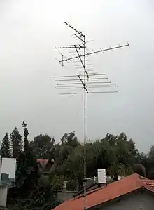
Antennas for use over much broader frequency ranges are achieved using further techniques. Adjustment of a matching network can, in principle, allow for any antenna to be matched at any frequency. Thus the small loop antenna built into most AM broadcast (medium wave) receivers has a very narrow bandwidth, but is tuned using a parallel capacitance which is adjusted according to the receiver tuning. On the other hand, log-periodic antennas are not resonant at any frequency but can be built to attain similar characteristics (including feedpoint impedance) over any frequency range. These are therefore commonly used (in the form of directional log-periodic dipole arrays) as television antennas.
Gain
Gain is a parameter which measures the degree of directivity of the antenna's radiation pattern. A high-gain antenna will radiate most of its power in a particular direction, while a low-gain antenna will radiate over a wide angle. The antenna gain, or power gain of an antenna is defined as the ratio of the intensity (power per unit surface area) radiated by the antenna in the direction of its maximum output, at an arbitrary distance, divided by the intensity radiated at the same distance by a hypothetical isotropic antenna which radiates equal power in all directions. This dimensionless ratio is usually expressed logarithmically in decibels, these units are called "decibels-isotropic" (dBi)


A second unit used to measure gain is the ratio of the power radiated by the antenna to the power radiated by a half-wave dipole antenna ; these units are called "decibels-dipole" (dBd)


Since the gain of a half-wave dipole is 2.15 dBi and the logarithm of a product is additive, the gain in dBi is just 2.15 decibels greater than the gain in dBd

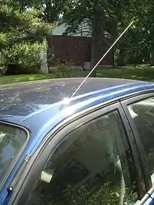
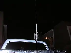
High-gain antennas have the advantage of longer range and better signal quality, but must be aimed carefully at the other antenna. An example of a high-gain antenna is a parabolic dish such as a satellite television antenna. Low-gain antennas have shorter range, but the orientation of the antenna is relatively unimportant. An example of a low-gain antenna is the whip antenna found on portable radios and cordless phones. Antenna gain should not be confused with amplifier gain, a separate parameter measuring the increase in signal power due to an amplifying device placed at the front-end of the system, such as a low-noise amplifier.
Effective area or aperture
The effective area or effective aperture of a receiving antenna expresses the portion of the power of a passing electromagnetic wave which the antenna delivers to its terminals, expressed in terms of an equivalent area. For instance, if a radio wave passing a given location has a flux of 1 pW / m2 (10−12 Watts per square meter) and an antenna has an effective area of 12 m2, then the antenna would deliver 12 pW of RF power to the receiver (30 microvolts RMS at 75 Ohms). Since the receiving antenna is not equally sensitive to signals received from all directions, the effective area is a function of the direction to the source.
Due to reciprocity (discussed above) the gain of an antenna used for transmitting must be proportional to its effective area when used for receiving. Consider an antenna with no loss, that is, one whose electrical efficiency is 100%. It can be shown that its effective area averaged over all directions must be equal to λ2/4π, the wavelength squared divided by 4π. Gain is defined such that the average gain over all directions for an antenna with 100% electrical efficiency is equal to 1. Therefore, the effective area Aeff in terms of the gain G in a given direction is given by:

For an antenna with an efficiency of less than 100%, both the effective area and gain are reduced by that same amount. Therefore, the above relationship between gain and effective area still holds. These are thus two different ways of expressing the same quantity. Aeff is especially convenient when computing the power that would be received by an antenna of a specified gain, as illustrated by the above example.
Radiation pattern

The radiation pattern of an antenna is a plot of the relative field strength of the radio waves emitted by the antenna at different angles in the far-field. It is typically represented by a three-dimensional graph, or polar plots of the horizontal and vertical cross sections. The pattern of an ideal isotropic antenna, which radiates equally in all directions, would look like a sphere. Many nondirectional antennas, such as monopoles and dipoles, emit equal power in all horizontal directions, with the power dropping off at higher and lower angles; this is called an omnidirectional pattern and when plotted looks like a torus or donut.
The radiation of many antennas shows a pattern of maxima or "lobes" at various angles, separated by "nulls", angles where the radiation falls to zero. This is because the radio waves emitted by different parts of the antenna typically interfere, causing maxima at angles where the radio waves arrive at distant points in phase, and zero radiation at other angles where the radio waves arrive out of phase. In a directional antenna designed to project radio waves in a particular direction, the lobe in that direction is designed larger than the others and is called the "main lobe". The other lobes usually represent unwanted radiation and are called "sidelobes". The axis through the main lobe is called the "principal axis" or "boresight axis".
The polar diagrams (and therefore the efficiency and gain) of Yagi antennas are tighter if the antenna is tuned for a narrower frequency range, e.g. the grouped antenna compared to the wideband. Similarly, the polar plots of horizontally polarized yagis are tighter than for those vertically polarized.[18]
Field regions
The space surrounding an antenna can be divided into three concentric regions: The reactive near-field (also called the inductive near-field), the radiating near-field (Fresnel region) and the far-field (Fraunhofer) regions. These regions are useful to identify the field structure in each, although the transitions between them are gradual, and there are no precise boundaries.
The far-field region is far enough from the antenna to ignore its size and shape: It can be assumed that the electromagnetic wave is purely a radiating plane wave (electric and magnetic fields are in phase and perpendicular to each other and to the direction of propagation). This simplifies the mathematical analysis of the radiated field.
Efficiency
Efficiency of a transmitting antenna is the ratio of power actually radiated (in all directions) to the power absorbed by the antenna terminals. The power supplied to the antenna terminals which is not radiated is converted into heat. This is usually through loss resistance in the antenna's conductors, or loss between the reflector and feed horn of a parabolic antenna.
Antenna efficiency is separate from impedance matching, which may also reduce the amount of power radiated using a given transmitter. If an SWR meter reads 150 W of incident power and 50 W of reflected power, that means 100 W have actually been absorbed by the antenna (ignoring transmission line losses). How much of that power has actually been radiated cannot be directly determined through electrical measurements at (or before) the antenna terminals, but would require (for instance) careful measurement of field strength. The loss resistance and efficiency of an antenna can be calculated once the field strength is known, by comparing it to the power supplied to the antenna.
The loss resistance will generally affect the feedpoint impedance, adding to its resistive component. That resistance will consist of the sum of the radiation resistance Rr and the loss resistance Rloss. If a current I is delivered to the terminals of an antenna, then a power of I2 Rr will be radiated and a power of I2 Rloss will be lost as heat. Therefore, the efficiency of an antenna is equal to Rr⁄(Rr + Rloss). Only the total resistance Rr + Rloss can be directly measured.
According to reciprocity, the efficiency of an antenna used as a receiving antenna is identical to its efficiency as a transmitting antenna, described above. The power that an antenna will deliver to a receiver (with a proper impedance match) is reduced by the same amount. In some receiving applications, the very inefficient antennas may have little impact on performance. At low frequencies, for example, atmospheric or man-made noise can mask antenna inefficiency. For example, CCIR Rep. 258-3 indicates man-made noise in a residential setting at 40 MHz is about 28 dB above the thermal noise floor. Consequently, an antenna with a 20 dB loss (due to inefficiency) would have little impact on system noise performance. The loss within the antenna will affect the intended signal and the noise/interference identically, leading to no reduction in signal to noise ratio (SNR).
Antennas which are not a significant fraction of a wavelength in size are inevitably inefficient due to their small radiation resistance. AM broadcast radios include a small loop antenna for reception which has an extremely poor efficiency. This has little effect on the receiver's performance, but simply requires greater amplification by the receiver's electronics. Contrast this tiny component to the massive and very tall towers used at AM broadcast stations for transmitting at the very same frequency, where every percentage point of reduced antenna efficiency entails a substantial cost.
The definition of antenna gain or power gain already includes the effect of the antenna's efficiency. Therefore, if one is trying to radiate a signal toward a receiver using a transmitter of a given power, one need only compare the gain of various antennas rather than considering the efficiency as well. This is likewise true for a receiving antenna at very high (especially microwave) frequencies, where the point is to receive a signal which is strong compared to the receiver's noise temperature. However, in the case of a directional antenna used for receiving signals with the intention of rejecting interference from different directions, one is no longer concerned with the antenna efficiency, as discussed above. In this case, rather than quoting the antenna gain, one would be more concerned with the directive gain, or simply directivity which does not include the effect of antenna (in)efficiency. The directive gain of an antenna can be computed from the published gain divided by the antenna's efficiency. In equation form, gain = directivity × efficiency.
Polarization
The polarization of an antenna refers to the orientation of the electric field of the radio wave transmitted by it, and is determined by the physical structure of the antenna and its orientation. For instance, an antenna composed of a linear conductor (such as a dipole or whip antenna) oriented vertically will result in vertical polarization; if turned on its side the same antenna's polarization will be horizontal.
Reflections generally affect polarization. Radio waves reflected off the ionosphere can change the wave's polarization. For line-of-sight communications or ground wave propagation, horizontally or vertically polarized transmissions generally remain in about the same polarization state at the receiving location. Using a vertically polarized antenna to receive a horizontally polarized wave (or visa-versa) results in relatively poor reception.
An antenna's polarization can sometimes be inferred directly from its geometry. When the antenna's conductors viewed from a reference location appear along one line, then the antenna's polarization will be linear in that very direction. In the more general case, the antenna's polarization must be determined through analysis. For instance, a turnstile antenna mounted horizontally (as is usual), from a distant location on earth, appears as a horizontal line segment, so its radiation received there is horizontally polarized. But viewed at a downward angle from an airplane, the same antenna does not meet this requirement; in fact its radiation is elliptically polarized when viewed from that direction. In some antennas the state of polarization will change with the frequency of transmission. The polarization of a commercial antenna is an essential specification.
In the most general case, polarization is elliptical, meaning that over each cycle the electric field vector traces out an ellipse. Two special cases are linear polarization (the ellipse collapses into a line) as discussed above, and circular polarization (in which the two axes of the ellipse are equal). In linear polarization the electric field of the radio wave oscillates along one direction. In circular polarization, the electric field of the radio wave rotates around the axis of propagation. Circular or elliptically polarized radio waves are designated as right-handed or left-handed using the "thumb in the direction of the propagation" rule. Note that for circular polarization, optical researchers use the opposite right hand rule from the one used by radio engineers.
It is best for the receiving antenna to match the polarization of the transmitted wave for optimum reception. Otherwise there will be a loss of signal strength: when a linearly polarized antenna receives linearly polarized radiation at a relative angle of θ, then there will be a power loss of cos2θ. A circularly polarized antenna can be used to equally well match vertical or horizontal linear polarizations, suffering a 3 dB signal reduction. However it will be blind to a circularly polarized signal of the opposite orientation!
Impedance matching
Maximum power transfer requires matching the impedance of an antenna system (as seen looking into the transmission line) to the complex conjugate of the impedance of the receiver or transmitter. In the case of a transmitter, however, the desired matching impedance might not correspond to the dynamic output impedance of the transmitter as analyzed as a source impedance but rather the design value (typically 50 Ohms) required for efficient and safe operation of the transmitting circuitry. The intended impedance is normally resistive but a transmitter (and some receivers) may have additional adjustments to cancel a certain amount of reactance in order to "tweak" the match. When a transmission line is used in between the antenna and the transmitter (or receiver) one generally would like an antenna system whose impedance is resistive and near the characteristic impedance of that transmission line in order to minimize the standing wave ratio (SWR) and the increase in transmission line losses it entails, in addition to matching the impedance that the transmitter (or receiver) expects.
Antenna tuning, in the context of modifying the antenna itself, generally refers only to cancellation of any reactance seen at the antenna terminals, leaving only a resistive impedance which might or might not be exactly the desired impedance (that of the transmission line). Although an antenna may be designed to have a purely resistive feedpoint impedance (such as a dipole 97% of a half wavelength long) this might not be exactly true at the frequency that it is eventually used at. In some cases the physical length of the antenna can be "trimmed" to obtain a pure resistance. On the other hand, the addition of a series inductance or parallel capacitance can be used to cancel a residual capacitative or inductive reactance, respectively. Antenna tuning used in the context of an impedance matching device called an antenna tuner involves both removal of reactance, and transforming the remaining resistance to be a match for the radio or feedline.
In some cases this is done in a more extreme manner, not simply to cancel a small amount of residual reactance, but to resonate an antenna whose resonance frequency is quite different from the intended frequency of operation. For instance, a "whip antenna" can be made significantly shorter than 1⁄4 wavelength long, for practical reasons, and then resonated using a so-called loading coil. This physically large inductor at the base of the antenna has an inductive reactance which is the opposite of the capacitative reactance that a short vertical antenna has at the desired operating frequency. The result is a pure resistance seen at feedpoint of the loading coil; that resistance is somewhat lower than would be desired to match commercial coax.
An additional problem is matching the remaining resistive impedance to the characteristic impedance of the transmission line. A general matching network (an antenna tuner or ATU) will have at least two adjustable elements to correct both components of impedance. Matching networks will have losses, and power restrictions when used for transmitting. Commercial antennas are generally designed to get an approximate match to standard coaxial cables, merely using a matching network to "tweak" any residual mismatch. Antennas of any kind may include a balun at their feedpoint to transform the resistive part of the impedance for a nearer match to the feedline.
Another extreme case of impedance matching occurs when using a small loop antenna (usually, but not always, for receiving) at a relatively low frequency where it appears almost as a pure inductor. Resonating such an inductor with a capacitor at the frequency of operation not only cancels the reactance but greatly magnifies the very small radiation resistance of such a loop. This is implemented in most AM broadcast receivers, with a small ferrite loop antenna resonated by a capacitor which is varied along with the receiver tuning in order to maintain resonance over the AM broadcast band
Effect of ground
Ground reflections is one of the common types of multipath.[19][20][21]
The radiation pattern and even the driving point impedance of an antenna can be influenced by the dielectric constant and especially conductivity of nearby objects. For a terrestrial antenna, the ground is usually one such object of importance. The antenna's height above the ground, as well as the electrical properties (permittivity and conductivity) of the ground, can then be important. Also, in the particular case of a monopole antenna, the ground (or an artificial ground plane) serves as the return connection for the antenna current thus having an additional effect, particularly on the impedance seen by the feed line.
When an electromagnetic wave strikes a plane surface such as the ground, part of the wave is transmitted into the ground and part of it is reflected, according to the Fresnel coefficients. If the ground is a very good conductor then almost all of the wave is reflected (180° out of phase), whereas a ground modeled as a (lossy) dielectric can absorb a large amount of the wave's power. The power remaining in the reflected wave, and the phase shift upon reflection, strongly depend on the wave's angle of incidence and polarization. The dielectric constant and conductivity (or simply the complex dielectric constant) is dependent on the soil type and is a function of frequency.
For very low frequencies to high frequencies (< 30 MHz), the ground behaves as a lossy dielectric,[22] thus the ground is characterized both by a conductivity[23] and permittivity (dielectric constant) which can be measured for a given soil (but is influenced by fluctuating moisture levels) or can be estimated from certain maps. At lower frequencies the ground acts mainly as a good conductor, which AM middle wave broadcast (0.5–1.6 MHz) antennas depend on.
At frequencies between 3 and 30 MHz, a large portion of the energy from a horizontally polarized antenna reflects off the ground, with almost total reflection at the grazing angles important for ground wave propagation. That reflected wave, with its phase reversed, can either cancel or reinforce the direct wave, depending on the antenna height in wavelengths and elevation angle (for a sky wave).
On the other hand, vertically polarized radiation is not well reflected by the ground except at grazing incidence or over very highly conducting surfaces such as sea water.[24] However the grazing angle reflection important for ground wave propagation, using vertical polarization, is in phase with the direct wave, providing a boost of up to 6 dB, as is detailed below.

At VHF and above (> 30 MHz) the ground becomes a poorer reflector. However it remains a good reflector especially for horizontal polarization and grazing angles of incidence. That is important as these higher frequencies usually depend on horizontal line-of-sight propagation (except for satellite communications), the ground then behaving almost as a mirror.
The net quality of a ground reflection depends on the topography of the surface. When the irregularities of the surface are much smaller than the wavelength, the dominant regime is that of specular reflection, and the receiver sees both the real antenna and an image of the antenna under the ground due to reflection. But if the ground has irregularities not small compared to the wavelength, reflections will not be coherent but shifted by random phases. With shorter wavelengths (higher frequencies), this is generally the case.
Whenever both the receiving or transmitting antenna are placed at significant heights above the ground (relative to the wavelength), waves specularly reflected by the ground will travel a longer distance than direct waves, inducing a phase shift which can sometimes be significant. When a sky wave is launched by such an antenna, that phase shift is always significant unless the antenna is very close to the ground (compared to the wavelength).
The phase of reflection of electromagnetic waves depends on the polarization of the incident wave. Given the larger refractive index of the ground (typically n ≈ 2) compared to air (n = 1), the phase of horizontally polarized radiation is reversed upon reflection (a phase shift of radians or 180°). On the other hand, the vertical component of the wave's electric field is reflected at grazing angles of incidence approximately in phase. These phase shifts apply as well to a ground modeled as a good electrical conductor.

This means that a receiving antenna "sees" an image of the emitting antenna but with 'reversed' currents (opposite in direction/phase) if the emitting antenna is horizontally oriented (and thus horizontally polarized). However, the received current will be in the same absolute direction/phase if the emitting antenna is vertically oriented/polarized.
The actual antenna which is transmitting the original wave then also may receive a strong signal from its own image from the ground. This will induce an additional current in the antenna element, changing the current at the feedpoint for a given feedpoint voltage. Thus the antenna's impedance, given by the ratio of feedpoint voltage to current, is altered due to the antenna's proximity to the ground. This can be quite a significant effect when the antenna is within a wavelength or two of the ground. But as the antenna height is increased, the reduced power of the reflected wave (due to the inverse square law) allows the antenna to approach its asymptotic feedpoint impedance given by theory. At lower heights, the effect on the antenna's impedance is very sensitive to the exact distance from the ground, as this affects the phase of the reflected wave relative to the currents in the antenna. Changing the antenna's height by a quarter wavelength, then changes the phase of the reflection by 180°, with a completely different effect on the antenna's impedance.
The ground reflection has an important effect on the net far field radiation pattern in the vertical plane, that is, as a function of elevation angle, which is thus different between a vertically and horizontally polarized antenna. Consider an antenna at a height h above the ground, transmitting a wave considered at the elevation angle θ. For a vertically polarized transmission the magnitude of the electric field of the electromagnetic wave produced by the direct ray plus the reflected ray is:

Thus the power received can be as high as 4 times that due to the direct wave alone (such as when θ = 0), following the square of the cosine. The sign inversion for the reflection of horizontally polarized emission instead results in:

where:
- is the electrical field that would be received by the direct wave if there were no ground.
- θ is the elevation angle of the wave being considered.
- is the wavelength.
- is the height of the antenna (half the distance between the antenna and its image).


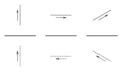
For horizontal propagation between transmitting and receiving antennas situated near the ground reasonably far from each other, the distances traveled by the direct and reflected rays are nearly the same. There is almost no relative phase shift. If the emission is polarized vertically, the two fields (direct and reflected) add and there is maximum of received signal. If the signal is polarized horizontally, the two signals subtract and the received signal is largely cancelled. The vertical plane radiation patterns are shown in the image at right. With vertical polarization there is always a maximum for θ = 0, horizontal propagation (left pattern). For horizontal polarization, there is cancellation at that angle. Note that the above formulae and these plots assume the ground as a perfect conductor. These plots of the radiation pattern correspond to a distance between the antenna and its image of 2.5 λ . As the antenna height is increased, the number of lobes increases as well.
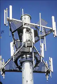
The difference in the above factors for the case of θ = 0 is the reason that most broadcasting (transmissions intended for the public) uses vertical polarization. For receivers near the ground, horizontally polarized transmissions suffer cancellation. For best reception the receiving antennas for these signals are likewise vertically polarized. In some applications where the receiving antenna must work in any position, as in mobile phones, the base station antennas use mixed polarization, such as linear polarization at an angle (with both vertical and horizontal components) or circular polarization.
On the other hand, analog television transmissions are usually horizontally polarized, because in urban areas buildings can reflect the electromagnetic waves and create ghost images due to multipath propagation. Using horizontal polarization, ghosting is reduced because the amount of reflection in the horizontal polarization off the side of a building is generally less than in the vertical direction. Vertically polarized analog television have been used in some rural areas. In digital terrestrial television such reflections are less problematic, due to robustness of binary transmissions and error correction.
Mutual impedance and interaction between antennas
Current circulating in one antenna generally induces a voltage across the feedpoint of nearby antennas or antenna elements. Such interactions can greatly affect the performance of a group of antennas.
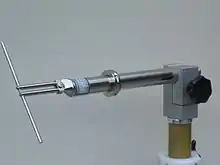
With a particular geometry, it is possible for the mutual impedance between nearby antennas to be zero. This is the case, for instance, between the crossed dipoles used in the turnstile antenna.
Antenna types
Antennas can be classified by operating principles or by their application.
See also
| Wikimedia Commons has media related to Antennas. |
| Wikisource has original text related to this article: |
- Category:Radio frequency antenna types
- Category:Radio frequency propagation
- Cellular repeater
- DXing
- Electromagnetism
- Mobile broadband modem
- Numerical Electromagnetics Code
- Radial (radio)
- Radio masts and towers
- RF connector
- Smart antenna
- TETRA
- Shortwave broadband antenna
Footnotes
- Since voltage lost due to radiation is typically small compared to the voltages required due to the antenna's surge impedance, and since dry air is a very good insulator, the antenna is often modeled as lossless: R = G = 0 . The essential loss or gain of voltage due to transmission or reception is usually inserted post-hoc, after the transmission line solutions, although it can be modeled as a small value of R at the expense of working with complex numbers.
References
- Graf, Rudolf F., ed. (1999). "Antenna". Modern Dictionary of Electronics. Newnes. p. 29. ISBN 978-0750698665.
- Hertz, H. (1889). "[no title cited]". Annalen der Physik und Chemie. 36.
- Marconi, G. (11 December 1909). "Wireless Telegraphic Communication". Nobel Lecture. Archived from the original on 4 May 2007.
"Physics 1901–1921". Nobel Lectures. Amsterdam: Elsevier Publishing Company. 1967. pp. 196–222, 206. - Slyusar, Vadym (20–23 September 2011). The history of radio engineering's term "antenna" (PDF). VIII International Conference on Antenna Theory and Techniques (ICATT’11). Kyiv, Ukraine. pp. 83–85. Archived (PDF) from the original on 24 February 2014.
- Slyusar, Vadym (21–24 February 2012). An Italian period on the history of radio engineering's term "antenna" (PDF). 11th International Conference Modern Problems of Radio Engineering, Telecommunications, and Computer Science (TCSET’2012). Lviv-Slavske, Ukraine. p. 174. Archived (PDF) from the original on 24 February 2014.
- Slyusar, Vadym (June 2011). "Антенна: история радиотехнического термина" [The Antenna: A history of radio engineering’s term] (PDF). ПЕРВАЯ МИЛЯ / Last Mile: Electronics: Science, Technology, Business (in Russian). No. 6. pp. 52–64. Archived (PDF) from the original on 24 February 2014.
- "Media Advisory: Apply now to attend the ALMA Observatory inauguration". ESO press release. Archived from the original on 6 December 2012. Retrieved 4 December 2012.
- Elliott, Robert S. (1981). Antenna Theory and Design (1st ed.). Wyle. p. 3.
- Smith, Carl (1969). Standard Broadcast Antenna Systems. Cleveland, Ohio: Smith Electronics. p. 2-1212.
- Lonngren, Karl Erik; Savov, Sava V.; Jost, Randy J. (2007). Fundamentals of Electomagnetics With Matlab (2nd ed.). SciTech Publishing. p. 451. ISBN 978-1891121586.
- Stutzman, Warren L.; Thiele, Gary A. (2012). Antenna Theory and Design (3rd ed.). John Wiley & Sons. pp. 560–564. ISBN 978-0470576649.
- Hall, Gerald, ed. (1991). The ARRL Antenna Book (15th ed.). ARRL. p. 24. ISBN 978-0-87259-206-3.
- Hall 1991, p. 25.
- Hall 1991, pp. 31-32.
- Slyusar, V. I. (17–21 September 2007). 60 Years of Electrically Small Antenna Theory (PDF). 6th International Conference on Antenna Theory and Techniques. Sevastopol, Ukraine. pp. 116–118. Archived (PDF) from the original on 28 August 2017. Retrieved 2 September 2017.
- Raines, Jeremy Keith (2007). Folded Unipole Antennas: Theory and applications. Electronic Engineering (1st ed.). McGraw Hill. ISBN 978-0-07-147485-6.ISBN 0-07-147485-4
- Schelkunoff, Sergei A.; Friis, Harald T. (July 1966) [1952]. Antennas: Theory and practice. John Wiley & Sons. LCCN 52-5083.
- "Aerial Polar Response Diagrams". ATV/Fracarro.
- Fixed Broadband Wireless System Design, p. 130, at Google Books
- Monopole Antennas, p. 340, at Google Books
- Wireless and Mobile Communication, p. 37, at Google Books
- Silver, H. Ward, ed. (2011). ARRL Antenna Book. Newington, Connecticut: American Radio Relay League. p. 3-2. ISBN 978-0-87259-694-8.
- "M3 Map of Effective Ground Conductivity in the United States (a Wall-Sized Map), for AM Broadcast Stations". fcc.gov. 11 December 2015. Archived from the original on 18 November 2015. Retrieved 6 May 2018.
- Silver 2011, p. 3-23
![]() The dictionary definition of antenna at Wiktionary
The dictionary definition of antenna at Wiktionary