Double dabble
In computer science, the double dabble algorithm is used to convert binary numbers into binary-coded decimal (BCD) notation.[1][2] It is also known as the shift-and-add-3 algorithm, and can be implemented using a small number of gates in computer hardware, but at the expense of high latency.[3]
Algorithm
The algorithm operates as follows:
Suppose the original number to be converted is stored in a register that is n bits wide. Reserve a scratch space wide enough to hold both the original number and its BCD representation; n + 4×ceil(n/3) bits will be enough. It takes a maximum of 4 bits in binary to store each decimal digit.
Then partition the scratch space into BCD digits (on the left) and the original register (on the right). For example, if the original number to be converted is eight bits wide, the scratch space would be partitioned as follows:
100s Tens Ones   Original
0010 0100 0011   11110011
The diagram above shows the binary representation of 24310 in the original register, and the BCD representation of 243 on the left.
The scratch space is initialized to all zeros, and then the value to be converted is copied into the "original register" space on the right.
0000 0000 0000 11110011
The algorithm then iterates n times. On each iteration, any BCD digit which is at least 5 (0101 in binary) is incremented by 3 (0011); then the entire scratch space is left-shifted one bit. The increment ensures that a value of 5, incremented and left-shifted, becomes 16 (10000), thus correctly "carrying" into the next BCD digit.
Essentially, the algorithm operates by doubling the BCD value on the left each iteration and adding either one or zero according to the original bit pattern. Shifting left accomplishes both tasks simultaneously. If any digit is five or above, three is added to ensure the value "carries" in base 10.
The double-dabble algorithm, performed on the value 24310, looks like this:
0000 0000 0000   11110011   Initialization
0000 0000 0001   11100110   Shift
0000 0000 0011   11001100   Shift
0000 0000 0111   10011000   Shift
0000 0000 1010   10011000   Add 3 to ONES, since it was 7
0000 0001 0101   00110000   Shift
0000 0001 1000   00110000   Add 3 to ONES, since it was 5
0000 0011 0000   01100000   Shift
0000 0110 0000   11000000   Shift
0000 1001 0000   11000000   Add 3 to TENS, since it was 6
0001 0010 0001   10000000   Shift
0010 0100 0011   00000000   Shift
   2    4    3
       BCD
Now eight shifts have been performed, so the algorithm terminates. The BCD digits to the left of the "original register" space display the BCD encoding of the original value 243.
Another example for the double dabble algorithm – value 6524410.
 104  103  102   101  100    Original binary
0000 0000 0000 0000 0000   1111111011011100   Initialization
0000 0000 0000 0000 0001   1111110110111000   Shift left (1st)
0000 0000 0000 0000 0011   1111101101110000   Shift left (2nd)
0000 0000 0000 0000 0111   1111011011100000   Shift left (3rd)
0000 0000 0000 0000 1010   1111011011100000   Add 3 to 100, since it was 7
0000 0000 0000 0001 0101   1110110111000000   Shift left (4th)
0000 0000 0000 0001 1000   1110110111000000   Add 3 to 100, since it was 5
0000 0000 0000 0011 0001   1101101110000000   Shift left (5th)
0000 0000 0000 0110 0011   1011011100000000   Shift left (6th)
0000 0000 0000 1001 0011   1011011100000000   Add 3 to 101, since it was 6
0000 0000 0001 0010 0111   0110111000000000   Shift left (7th)
0000 0000 0001 0010 1010   0110111000000000   Add 3 to 100, since it was 7
0000 0000 0010 0101 0100   1101110000000000   Shift left (8th)
0000 0000 0010 1000 0100   1101110000000000   Add 3 to 101, since it was 5
0000 0000 0101 0000 1001   1011100000000000   Shift left (9th)
0000 0000 1000 0000 1001   1011100000000000   Add 3 to 102, since it was 5
0000 0000 1000 0000 1100   1011100000000000   Add 3 to 100, since it was 9
0000 0001 0000 0001 1001   0111000000000000   Shift left (10th)
0000 0001 0000 0001 1100   0111000000000000   Add 3 to 100, since it was 9
0000 0010 0000 0011 1000   1110000000000000   Shift left (11th)
0000 0010 0000 0011 1011   1110000000000000   Add 3 to 100, since it was 8
0000 0100 0000 0111 0111   1100000000000000   Shift left (12th)
0000 0100 0000 1010 0111   1100000000000000   Add 3 to 101, since it was 7
0000 0100 0000 1010 1010   1100000000000000   Add 3 to 100, since it was 7
0000 1000 0001 0101 0101   1000000000000000   Shift left (13th)
0000 1011 0001 0101 0101   1000000000000000   Add 3 to 103, since it was 8
0000 1011 0001 1000 0101   1000000000000000   Add 3 to 101, since it was 5
0000 1011 0001 1000 1000   1000000000000000   Add 3 to 100, since it was 5
0001 0110 0011 0001 0001   0000000000000000   Shift left (14th)
0001 1001 0011 0001 0001   0000000000000000   Add 3 to 103, since it was 6
0011 0010 0110 0010 0010   0000000000000000   Shift left (15th)
0011 0010 1001 0010 0010   0000000000000000   Add 3 to 102, since it was 6
0110 0101 0010 0100 0100   0000000000000000   Shift left (16th)
   6    5    2    4    4
            BCD
Sixteen shifts have been performed, so the algorithm terminates. The decimal value of the BCD digits is: 6*104 + 5*103 + 2*102 + 4*101 + 4*100 = 65244.
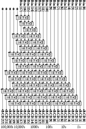
Parametric Verilog implementation of the double dabble binary to BCD converter[4]
// parametric Verilog implementation of the double dabble binary to BCD converter
// for the complete project, see
// https://github.com/AmeerAbdelhadi/Binary-to-BCD-Converter

module bin2bcd
 #( parameter                W = 18)  // input width
  ( input      [W-1      :0] bin   ,  // binary
    output reg [W+(W-4)/3:0] bcd   ); // bcd {...,thousands,hundreds,tens,ones}

  integer i,j;

  always @(bin) begin
    for(i = 0; i <= W+(W-4)/3; i = i+1) bcd[i] = 0;     // initialize with zeros
    bcd[W-1:0] = bin;                                   // initialize with input vector
    for(i = 0; i <= W-4; i = i+1)                       // iterate on structure depth
      for(j = 0; j <= i/3; j = j+1)                     // iterate on structure width
        if (bcd[W-i+4*j -: 4] > 4)                      // if > 4
          bcd[W-i+4*j -: 4] = bcd[W-i+4*j -: 4] + 4'd3; // add 3
  end

endmodule
Reverse double dabble
The algorithm is fully reversible. By applying the reverse double dabble algorithm a BCD number can be converted to binary. Reversing the algorithm is done by reversing the principle steps of the algorithm:
| Double dabble (Binary to BCD) |
Reverse double dabble (BCD to binary) |
|---|---|
| For each group of input four bits: If group >= 5 add 3 to group Left shift into the output digits |
Right shift into the output binary For each group of four input bits: If group >= 8 subtract 3 from group |
Reverse double dabble example
The reverse double dabble algorithm, performed on the three BCD digits 2-4-3, looks like this:
    BCD Input      Binary
                   Output
   2    4    3
 0010 0100 0011   00000000   Initialization
 0001 0010 0001   10000000   Shifted right
 0000 1001 0000   11000000   Shifted right
 0000 0110 0000   11000000   Subtracted 3 from 2nd group, because it was 9
 0000 0011 0000   01100000   Shifted right
 0000 0001 1000   00110000   Shifted right
 0000 0001 0101   00110000   Subtracted 3 from 3rd group, because it was 8
 0000 0000 1010   10011000   Shifted right
 0000 0000 0111   10011000   Subtracted 3 from 3rd group, because it was 10
 0000 0000 0011   11001100   Shifted right
 0000 0000 0001   11100110   Shifted right
 0000 0000 0000   11110011   Shifted right
==========================
                       24310
C implementation
The double dabble algorithm might look like this when implemented in C. Notice that this implementation is designed to convert an "input register" of any width, by taking an array as its parameter and returning a dynamically allocated string. Also notice that this implementation does not store an explicit copy of the input register in its scratch space, as the description of the algorithm did; copying the input register into the scratch space was just a pedagogical device.
#include <stdio.h>
#include <stdlib.h>
#include <string.h>

/*
   This function takes an array of n unsigned integers,
   each holding a value in the range [0, 65535],
   representing a number in the range [0, 2**(16n)-1].
   arr[0] is the most significant "digit".
   This function returns a new array containing the given
   number as a string of decimal digits.

   For the sake of brevity, this example assumes that
   calloc and realloc will never fail.
*/
void double_dabble(int n, const unsigned int *arr, char **result)
{
    int nbits = 16*n;         /* length of arr in bits */
    int nscratch = nbits/3;   /* length of scratch in bytes */
    char *scratch = calloc(1 + nscratch, sizeof *scratch);
    int i, j, k;
    int smin = nscratch-2;    /* speed optimization */

    for (i=0; i < n; ++i) {
        for (j=0; j < 16; ++j) {
            /* This bit will be shifted in on the right. */
            int shifted_in = (arr[i] & (1 << (15-j)))? 1: 0;

            /* Add 3 everywhere that scratch[k] >= 5. */
            for (k=smin; k < nscratch; ++k)
              scratch[k] += (scratch[k] >= 5)? 3: 0;

            /* Shift scratch to the left by one position. */
            if (scratch[smin] >= 8)
              smin -= 1;
            for (k=smin; k < nscratch-1; ++k) {
                scratch[k] <<= 1;
                scratch[k] &= 0xF;
                scratch[k] |= (scratch[k+1] >= 8);
            }

            /* Shift in the new bit from arr. */
            scratch[nscratch-1] <<= 1;
            scratch[nscratch-1] &= 0xF;
            scratch[nscratch-1] |= shifted_in;
        }
    }

    /* Remove leading zeros from the scratch space. */
    for (k=0; k < nscratch-1; ++k)
      if (scratch[k] != 0) break;
    nscratch -= k;
    memmove(scratch, scratch+k, nscratch+1);

    /* Convert the scratch space from BCD digits to ASCII. */
    for (k=0; k < nscratch; ++k)
      scratch[k] += '0';

    /* Resize and return the resulting string. */
    *result = realloc(scratch, nscratch+1);
    return;
}

/*
   This test driver should print the following decimal values:
   246
   16170604
   1059756703745
*/
int main(void)
{
    unsigned int arr[] = { 246, 48748, 1 };
    char *text = NULL;
    int i;
    for (i=0; i < 3; ++i) {
        double_dabble(i+1, arr, &text);
        printf("%s\n", text);
        free(text);
    }
    return 0;
}
VHDL implementation
library IEEE;
use IEEE.STD_LOGIC_1164.ALL;
use IEEE.numeric_std.all;


entity bin2bcd_12bit is
    Port ( binIN : in  STD_LOGIC_VECTOR (11 downto 0);
           ones : out  STD_LOGIC_VECTOR (3 downto 0);
           tens : out  STD_LOGIC_VECTOR (3 downto 0);
           hundreds : out  STD_LOGIC_VECTOR (3 downto 0);
           thousands : out  STD_LOGIC_VECTOR (3 downto 0)
          );
end bin2bcd_12bit;

architecture Behavioral of bin2bcd_12bit is

begin

bcd1: process(binIN)

  -- temporary variable
  variable temp : STD_LOGIC_VECTOR (11 downto 0);

  -- variable to store the output BCD number
  -- organized as follows
  -- thousands = bcd(15 downto 12)
  -- hundreds = bcd(11 downto 8)
  -- tens = bcd(7 downto 4)
  -- units = bcd(3 downto 0)
  variable bcd : UNSIGNED (15 downto 0) := (others => '0');

  -- by
  -- https://en.wikipedia.org/wiki/Double_dabble

  begin
    -- zero the bcd variable
    bcd := (others => '0');

    -- read input into temp variable
    temp(11 downto 0) := binIN;

    -- cycle 12 times as we have 12 input bits
    -- this could be optimized, we do not need to check and add 3 for the
    -- first 3 iterations as the number can never be >4
    for i in 0 to 11 loop

      if bcd(3 downto 0) > 4 then
        bcd(3 downto 0) := bcd(3 downto 0) + 3;
      end if;

      if bcd(7 downto 4) > 4 then
        bcd(7 downto 4) := bcd(7 downto 4) + 3;
      end if;

      if bcd(11 downto 8) > 4 then
        bcd(11 downto 8) := bcd(11 downto 8) + 3;
      end if;

      -- thousands can't be >4 for a 12-bit input number
      -- so don't need to do anything to upper 4 bits of bcd

      -- shift bcd left by 1 bit, copy MSB of temp into LSB of bcd
      bcd := bcd(14 downto 0) & temp(11);

      -- shift temp left by 1 bit
      temp := temp(10 downto 0) & '0';

    end loop;

    -- set outputs
    ones <= STD_LOGIC_VECTOR(bcd(3 downto 0));
    tens <= STD_LOGIC_VECTOR(bcd(7 downto 4));
    hundreds <= STD_LOGIC_VECTOR(bcd(11 downto 8));
    thousands <= STD_LOGIC_VECTOR(bcd(15 downto 12));

  end process bcd1;

end Behavioral;
VHDL testbench
LIBRARY ieee;
USE ieee.std_logic_1164.ALL;

ENTITY bin2bcd_12bit_test_file IS
END bin2bcd_12bit_test_file;

ARCHITECTURE behavior OF bin2bcd_12bit_test_file IS

    -- Component Declaration for the Unit Under Test (UUT)

    COMPONENT bin2bcd_12bit
    PORT(
         binIN : IN  std_logic_vector(11 downto 0);
         ones : OUT  std_logic_vector(3 downto 0);
         tens : OUT  std_logic_vector(3 downto 0);
         hundreds : OUT  std_logic_vector(3 downto 0);
	 thousands : OUT  std_logic_vector(3 downto 0)
        );
    END COMPONENT;

  -- WARNING: Please, notice that there is no need for a clock signal in the testbench, since the design is strictly
  --    combinational (or concurrent, in contrast to the C implementation which is sequential).
  -- This clock is here just for simulation; you can omit all clock references and process, and use "wait for ... ns"
  --    statements instead.

   --Inputs
   signal binIN : std_logic_vector(11 downto 0) := (others => '0');
   signal clk : std_logic := '0';  -- can be omitted

 	--Outputs
   signal ones : std_logic_vector(3 downto 0);
   signal tenths : std_logic_vector(3 downto 0);
   signal hunderths : std_logic_vector(3 downto 0);
   signal thousands : std_logic_vector(3 downto 0);

   -- Clock period definitions
   constant clk_period : time := 10 ns;  -- can be omitted

   -- Miscellaneous
   signal full_number : std_logic_vector(15 downto 0);

BEGIN

	-- Instantiate the Unit Under Test (UUT)
   uut: bin2bcd_12bit PORT MAP (
          binIN => binIN,
          ones => ones,
          tens => tenths,
          hundreds => hunderths,
	  thousands => thousands
        );

   -- Clock process definitions  -- the whole process can be omitted
   clk_process :process
   begin
		clk <= '0';
		wait for clk_period/2;
		clk <= '1';
		wait for clk_period/2;
   end process;

   -- Combine signals for full number
   full_number <= thousands & hunderths & tenths & ones;

   -- Stimulus process
   stim_proc: process
   begin
      -- hold reset state for 100 ns.
      wait for 100 ns;

      wait for clk_period*10;

      -- insert stimulus here
		-- should return 4095
		binIN <= X"FFF";
		wait for clk_period*10;  assert full_number = x"4095" severity error;  -- use "wait for ... ns;"

		-- should return 0
		binIN <= X"000";
		wait for clk_period*10;  assert full_number = x"0000" severity error;

		-- should return 2748
		binIN <= X"ABC";
		wait for clk_period*10;  assert full_number = x"2748" severity error;


      wait;
   end process;

END;
Optimized snippet Bin2BCD for SBA (VHDL)
-- /SBA: Program Details --===================================================--
-- Snippet: 16 bit Binary to BCD converter
-- Author: Miguel A. Risco-Castillo
-- Description: 16 bit to BCD converter using "Double Dabble" algorithm.
-- Before call you must fill "bin_in" with the appropriate value, after called,
-- the snippet put into the variable "bcd_out" the BCD result of the conversion.
-- Put the snippet in the routines section of the user program.
-- /SBA: End Program Details ---------------------------------------------------

-- /SBA: User Registers and Constants --======================================--
  variable bin_in  : unsigned(15 downto 0);      -- 16 bit input register
  variable bcd_out : unsigned(19 downto 0);      -- 20 bit output register
-- /SBA: End User Registers and Constants --------------------------------------

-- /SBA: User Program --======================================================--
-- /L:Bin2BCD
=> bcd_out := (others=>'0');
   if bin_in=0 then SBARet; end if; -- if zero then return
=> bcd_out(2 downto 0) := bin_in(15 downto 13); -- shl 3
   bin_in := bin_in(12 downto 0) & "000";
=> for j in 0 to 12 loop
     for i in 0 to 3 loop -- for nibble 0 to 3, last nibble do not need adjust
       if bcd_out(3+4*i downto 4*i)>4 then -- is nibble > 4?
         bcd_out(3+4*i downto 4*i):=bcd_out(3+4*i downto 4*i)+3; -- add 3 to nibble
       end if;
     end loop;
     bcd_out := bcd_out(18 downto 0) & bin_in(15); --shl
     bin_in := bin_in(14 downto 0) & '0';
   end loop;
   SBARet; -- return to main program
-- /SBA: End User Program ------------------------------------------------------
Historical
In the 1960s, the term double dabble was also used for a different mental algorithm, used by programmers to convert a binary number to decimal. It is performed by reading the binary number from left to right, doubling if the next bit is zero, and doubling and adding one if the next bit is one.[7] In the example above, 11110011, the thought process would be: "one, three, seven, fifteen, thirty, sixty, one hundred twenty-one, two hundred forty-three", the same result as that obtained above.
See also
- Lookup table – an alternate approach to perform conversion
References
- Gao, Shuli; Al-Khalili, D.; Chabini, N. (June 2012), "An improved BCD adder using 6-LUT FPGAs", IEEE 10th International New Circuits and Systems Conference (NEWCAS 2012), pp. 13–16, doi:10.1109/NEWCAS.2012.6328944, S2CID 36909518
- "Binary-to-BCD Converter: "Double-Dabble Binary-to-BCD Conversion Algorithm"" (PDF). Archived from the original (PDF) on 2012-01-31.
- Véstias, Mario P.; Neto, Horatio C. (March 2010), "Parallel decimal multipliers using binary multipliers", VI Southern Programmable Logic Conference (SPL 2010), pp. 73–78, doi:10.1109/SPL.2010.5483001, S2CID 28360570
- Abdelhadi, Ameer (2019-07-07), AmeerAbdelhadi/Binary-to-BCD-Converter, retrieved 2020-03-03
- Abdelhadi, Ameer (2019-07-07), AmeerAbdelhadi/Binary-to-BCD-Converter, retrieved 2020-03-03
- "SBA". sba.accesus.com. Retrieved 2016-12-31.
The Simple Bus Architecture
- Godse, Deepali A.; Godse, Atul P. (2008). Digital Techniques. Pune, India: Technical Publications. p. 4. ISBN 978-8-18431401-4.
Further reading
- Falconer, Charles "Chuck" B. (2004-04-16). "An Explanation of the Double-Dabble Bin-BCD Conversion Algorithm". Archived from the original on 2009-03-25.
