Epson HX-20
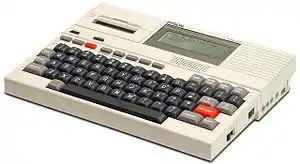
The Epson HX-20 (also known as the HC-20) was the first "true" laptop computer.[4][1][2] It was invented in July 1980 by Yukio Yokozawa, who worked for Suwa Seikosha, a branch of Japanese company Seiko (now Seiko Epson), receiving a patent for the invention.[5] It was announced in 1981 as the HC-20 in Japan,[1] and was introduced by Epson in North America as the HX-20 at the 1981 COMDEX computer show in Las Vegas, where it drew significant attention for its portability.[6] It had a mass-market release in July 1982, as the HC-20 in Japan[1] and as the Epson HX-20 in North America.[2] The size of an A4 notebook and weighing 1.6 kg, it was hailed by BusinessWeek magazine as the "fourth revolution in personal computing".
 The Epson HX-20 | |
| Also known as | HC-20 |
|---|---|
| Manufacturer | Seiko Epson |
| Release date | July 1982[1][2][3] |
| Introductory price | US$795 (today $2040.76) |
| CPU | two Hitachi 6301 CPUs at 614 kHz |
| Memory | 16 kB RAM expandable to 32 kB 32 kB ROM expandable to 64 kB |
| Display | 4 lines x 20 characters LCD |
| Graphics | 120 × 32-pixel |
| Input | full-transit keyboard |
| Power | rechargeable nickel-cadmium batteries |
| Dimensions | A4 Sized |
| Mass | approximately 1.6 kg |
Features
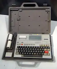
Epson advertised the HX-20 with a photograph and photo editing of the computer on two facing magazine pages with the headline "Actual size".[7] With about the footprint of an A4 size page, the Epson HX-20 features a full-transit keyboard, rechargeable nickel-cadmium batteries, a built-in 120 × 32-pixel LCD which allowed 4 lines of 20 characters, a calculator-size dot-matrix printer, the EPSON BASIC programming language, two Hitachi 6301 CPUs at 614 kHz[8] which is essentially an enhanced Motorola 6801,[9] 16 kB RAM expandable to 32 kB, two RS-232 ports at a maximum of 4800 bits/s for the first 8-pin DIN connector intended for modem or serial printer with the second port capable of 38,400 bits/s using a 5-pin DIN connector which was mainly for use with external floppy drive and video display[8] an early concept of docking station, a 300 bit/s acoustic coupler was available,[8] built-in microcassette drive, barcode reader connector.[8] Uses a proprietary operating system, which consists of the EPSON BASIC interpreter and a monitor program, and weighs approximately 1.6 kg. Known colours of the machine are silver and cream, while some prototypes were dark grey. The HX-20 was supplied with a grey or brown carry case. An external acoustic coupler, the CX-20, was available for the HX-20, as was an external floppy disk drive, the TF-20, and an external speech synthesis Augmentative Communication Device (ACD), 'RealVoice'. Another extension was the serially connected 40 × 24 character video. It used a special protocol, EPSP,[10] which was also used by the external floppy disk drive. The battery life of the HX-20 was approximately 50 hours running BASIC and less using the microcassette, printer or RS-232.[8] Data integrity could be preserved in the 4.0 - 6.0 V range.[8] The power supply was rated for 8 W.[8] Operating and charging it would tolerate 5 - 35 °C.[8] Data integrity could be preserved at -5 - 40 °C.[8] The HX-20 could be stored between -20 - 60 °C.[8]
The later, more popular TRS-80 Model 100 line, designed by Kyocera, owed much to the design of the HX-20.
Reception
BYTE in September 1983 wrote that the HX-20, available in the United States for about a year, had been unsuccessful because of the lack of software or accessories. The review noted that Epson had included the formerly $160 microcassette drive in the standard $795 configuration, as well as bundling a simple word processor. BYTE praised the printer as "nothing short of amazing", but criticized the lack of an operating system for cassette storage and said that compared to the TRS-80 Model 100's display, "the HX-20 looks primitive".[11]
LCD
The LCD is 120×32 pixels and is controlled by six μPD7227 LCD controller ICs each responsible for 40×16 pixels of the LCD. The μPD7227 uses a serial protocol and has two memory banks for switching between rows 0-7 and 8-15. It features multiple modes, including "Write", "Read", "AND", "OR" and "Character". The "character" mode draws characters from a built-in character map. Each bank is 40 bytes with bit 6 of the address determining the bank and even though the address can be up to 127, nothing will happen when trying to access data outside the banks. If the pointer action in a command is set to decrement and the pointer is at 0, the pointer will wrap to 127.
Monitor
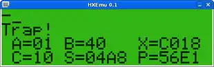
The Monitor program can be accessed via the main menu on startup by pressing 1, by typing the command "MON" in BASIC or by causing a trap, i.e. writing/reading to/from protected addresses or executing an illegal instruction. In the case of a trap, "Trap!" will be displayed in the Monitor and the user can use it for debugging.
When entering Monitor it shows a prompt on the first line, "Trap!" on the second line (if entered via a trap) and the CPU registers as they were right before the Monitor was entered on the third and fourth lines. These registers are A (Accumulator A), B (Accumulator B), X (Index Register), C (Condition Code Register), S (Stack Pointer) and P (Program Counter).
Monitor can be used for reading and writing memory, modifying CPU registers, running code at specific addresses in memory, saving/loading memory to/from a plugin option, etc. This is very useful for debugging programs written in machine code in difference to programs written in the EPSON BASIC programming language.
Commands
| Command | Syntax | Description |
|---|---|---|
| S (Set) | S<addr> [old] [new] | Writes the 8-bit value "new" (in hex) to 16-bit address <addr>. Entering only the address and pressing enter will make the old value at the address appear and the cursor put after the old value for entering a value. |
| D (Dump) | D<addr> | Dumps the values from addresses <addr> to <addr + 14> to the display. |
| G (Go) | G<addr>,<breakpoint> | Sets the programme counter to the 16-bit address <addr> and will return to Monitor before the breakpoint address <breakpoint> is executed. |
| X (Examine) | X | Allows the user to display and change the contents of each register. The RETURN key applies the changed value (if any) and jumps between registers. Typing a non-hexadecimal character exits this command. |
| R (Read) | R<device>,<filename> | Transfer data from an external storage to memory. <device> can be any of M (microcassette), C (external cassette) and P (ROM cartridge). The memory address is specified using the "A (Address)" command. |
| W (Write) | W<device>,<filename> | Transfer data from memory specified by the "A (Address)" command to an external storage. See "R (Read)" for more information. ROM cartridge is not supported by this command. |
| V (Verify) | V<device>,<filename> | Verifies data transferred to an external storage against the memory specified by the "A (Address)" command. See "R (Read)" for more information. ROM cartridge is not supported by this command. |
| A (Address) | A | Specify an address range for commands R, W and V. The user will be prompted with T (Top address), L (Last address), O (Offset value) and E (Entrypoint). Offset and entrypoint values are only used by the "W (Write)" and "V (Verify)" commands. |
| K (Key set) | K<text> | Enter a sequence of keys to be pressed automatically on power up (and reset). Press CTRL+@ to stop. A maximum of 18 characters can be entered and function keys counts as two characters. |
| B (Back) | B | Return to the procedure from which Monitor was called. |
Expansion port
The expansion port allows hardware to connect directly to the master processor's memory bus, exposing the 16-bit address bus, 8-bit data bus and control signals. An external device can add ROMs, RAM or MMIO-devices to the master CPU's address space. The address range 0x4000-0x5FFF has no internal mapping and is thus a good range for external hardware, but the internal ROMs (0x6000-0xFFFF) can be disabled as well using the ROM enable pin so the entire range 0x4000-0xFFFF can be used.
There's an "expansion unit" which contains sockets for extra RAM and ROMs which can be mapped to various areas in the address space using a DIP switch, even replacing the BASIC interpreter ROMs. Some software distributed as ROMs were designed to be used in the expansion unit.
| Pin | Name | Direction | Description | Pin | Name | Direction | Description |
|---|---|---|---|---|---|---|---|
| 1 | Vb | - | +5V | 21 | ADDR6 | OUT | Address line 6 |
| 2 | NMI# | - | Master/Slave CPU NMI-signal | 22 | ADDR7 | OUT | Address line 7 |
| 3 | +5V | - | Logic voltage | 23 | ADDR8 | OUT | Address line 8 |
| 4 | +5V | - | Logic voltage | 24 | ADDR9 | OUT | Address line 9 |
| 5 | DATA7 | IN/OUT | Data line 7 | 25 | ADDR10 | OUT | Address line 10 |
| 6 | DATA6 | IN/OUT | Data line 6 | 26 | ADDR11 | OUT | Address line 11 |
| 7 | DATA5 | IN/OUT | Data line 5 | 27 | ADDR12 | OUT | Address line 12 |
| 8 | DATA4 | IN/OUT | Data line 4 | 28 | ADDR13 | OUT | Address line 13 |
| 9 | DATA3 | IN/OUT | Data line 3 | 29 | ADDR14 | OUT | Address line 14 |
| 10 | DATA2 | IN/OUT | Data line 2 | 30 | ADDR15 | OUT | Address line 15 |
| 11 | DATA1 | IN/OUT | Data line 1 | 31 | R | OUT | Reset |
| 12 | DATA0 | IN/OUT | Data line 0 | 32 | R/W | OUT | Read (low)/Write (high) |
| 13 | IOCS# | OUT | I/O chip select | 33 | R (RAM)# | OUT | RAM reset |
| 14 | Vc | - | RAM backup voltage (+3V) | 34 | E | OUT | ENABLE signal |
| 15 | ADDR0 | OUT | Address line 0 | 35 | ROM E | IN | ROM enable |
| 16 | ADDR1 | OUT | Address line 1 | 36 | INTEX# | IN | External interrupt signal |
| 17 | ADDR2 | OUT | Address line 2 | 37 | GND | - | Signal ground |
| 18 | ADDR3 | OUT | Address line 3 | 38 | GND | - | Signal ground |
| 19 | ADDR4 | OUT | Address line 4 | 39 | CG | - | Chassis ground |
| 20 | ADDR5 | OUT | Address line 5 | 40 | CG | - | Chassis ground |
Memory map
| Start | End | Description |
|---|---|---|
| 0000 | 001F | Internal registers |
| 0020 | 003F | I/O select |
| 0040 | 007F | RTC registers + RAM |
| 0080 | 3FFF | RAM |
| 4000 | 5FFF | Used by expansion unit |
| 6000 | 7FFF | ROM #4 (Option ROM) |
| 8000 | 9FFF | ROM #3 |
| A000 | BFFF | ROM #2 |
| C000 | DFFF | ROM #1 |
| E000 | FFFF | ROM #0 |
ROM #0 and #1 are known as the I/O ROMs, handling system reset and providing functions for using the LCD, keyboard, clock, printer, speaker, serial communication, etc. The I/O ROMs are equivalent to the BIOS in modern PCs. ROM #0 also contains the interrupt vector table at FFF0-FFFF. FFFE-FFFF determines what the program counter should be set to on power up or reset. In the standard set of ROMs for the HX-20, this value is E000, the start of ROM #0.
ROM #2 and #3 contains the BASIC interpreter. If the BASIC ROMs are removed from the motherboard, the BASIC option in the main menu will disappear, leaving only MONITOR. This is because ROM #3 contains a program header which is detected by the menu routines. This works the same for all user-created programs, except the program type is different.
The Expansion unit added up to 16 kByte of RAM and two ROM sockets. The latter could only be used by switching off the internal BASIC ROMS.[12]
Similar Epson models
- HC-80 (Japanese version of the PX-8)
- HC-88 (Japanese version of the PX-8)
- HX-40 (American version of the PX-4)
- HX-45 (American version of the PX-4)
- KX-1
- PX-16 (IBM PC compatible portable, cartridges compatible with PX-4)
- PX-4 (successor of the HX-20, with larger screen and CP/M compatible like the PX-8)
- PX-8 (Geneva)
- EHT-30, EHT-40
Problems
A common complaint found in most HX-20 computers today is the failure of the internal Ni-Cd rechargeable battery pack. The battery pack is easily replaced by a NiMH (or equivalent) battery pack. Changing the battery pack is not generally considered to reduce the collectible value of the computer, as doing so does not damage any internals.
An easy fix for replacement batteries is to use four AA cells in a holder secured on the inside. The leads can be easily soldered on to the connector from an original battery. It can also work with a lantern battery on alligator clips.
References
- "Shinshu Seiki/Suwa Seikosha HC-20". IPSJ Computer Museum. Retrieved 19 June 2019.
- Michael R. Peres, The Focal Encyclopedia of Photography, page 306, Taylor & Francis
- "Epson HX-20 laptop computer". Museum of Technology. Retrieved 9 September 2016.
- "Epson SX-20 Promotional Brochure" (PDF). Epson America, Inc. 1987. Retrieved 2 November 2008.
- FR2487094A1 patent: Notebook computer system small
- Epson HX-20, Old Computers
- Advertisement (December 1982). "Actual size". BYTE. pp. 260–261. Retrieved 19 October 2013.
- HX-20 Operations Manual
- jrok.om - Replacement CUS60, CUS63 and some CUS64
- "C-20 PROTOCOL". 19 November 1982. Retrieved 19 June 2019.
- Ramsey, David (September 1983). "Epson's HX-20 and Texas Instruments' CC-40". BYTE. p. 193. Retrieved 20 October 2013.
- Technical Support Document number 72a, Using the Epson HX-20 expansion unit
External links
| Wikimedia Commons has media related to Epson HX-20. |
- Epson HX-20 documentation, photos and software
- Epson's HX-20 manual and additional material
- HX-20 utility and game programs
- 'HXTape' program to read and write tapes via a soundcard
- old-computers.com article on the HX-20
- 1983 Epson HX-20 computer., (evaluation) David H. Ahl., CREATIVE COMPUTING VOL. 9, NO. 3 / MARCH 1983 / PAGE 101
- vintage-computer.com article about the HX-20
- https://www.youtube.com/watch?v=o-F_hL1bZsw The World's First Laptop - Epson HX-20 / HC-20
- flashx20: Simulation of HX-20 external floppy disk drives and external monitor on a PC