DIN connector
A DIN connector is an electrical connector that was originally standardized in the early 1970s[1] by the Deutsches Institut für Normung (DIN), the German national standards organization. There are DIN standards for various different connectors, therefore the term "DIN connector" alone does not unambiguously identify any particular type of connector unless the document number of the relevant DIN standard is added (e.g., "DIN 45322 connector"). Some DIN connector standards are:
- DIN 41524, for circular connectors often used for audio signals or some digital signals like MIDI
- DIN 41612, rectangular connectors used to connect plug-in cards to a back plane or motherboard
- DIN 41652 D-subminiature connectors used for computer data and video
- DIN 41585 automotive coaxial connectors

In the context of consumer electronics, the term "DIN connector" commonly refers to a member of a family of circular connectors that were initially standardized by DIN for analog audio signals. Some of these connectors have also been used in analog video applications, for power connections and for digital interfaces such as MIDI (DIN 41524) or the IBM PC keyboard and IBM AT keyboard connectors (DIN 41524, later PS/2 connectors for keyboard and mouse are Mini-DIN connectors). The original DIN standards for these connectors are no longer in print and have been replaced with the equivalent international standard IEC 60130-9.[2]
While DIN connectors appear superficially similar to the professional XLR connectors, they are not compatible.
Circular connectors
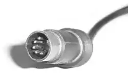
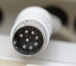
All male connectors (plugs) of this family of connectors feature a 13.2 mm diameter metal shield with a notch that limits the orientation in which plug and socket can mate. A range of connectors of the same form that differ only in their pin configuration exist and have been standardized, originally in DIN 41524 / IEC/DIN EN 60130-9 (3-pin at 90° and 5-pin at 45°), DIN 45322 (5-pin and 6-pin at 60°), DIN 45329 (7-pin at 45°), DIN 45326 / IEC/DIN EN 60130-9 (8-pin at 45°), and other standards for a range of different applications, including the following examples:


The plugs consist of a circular shielding metal skirt protecting a number of straight round pins. The pins are 1.45 mm in diameter and equally spaced (at 90°, 72°, 60° or 45° angles) in a 7.0 mm diameter circle. The skirt is keyed to ensure that the plug is inserted with the correct orientation, and to prevent damage to the pins. The basic design also ensures that the shielding is connected between socket and plug prior to any signal path connection being made. However, as the keying is consistent across all connectors, it does not prevent incompatible connectors from mating, which can lead to damage; this is changed in Mini-DIN, which keys different connectors. Additionally, some "domino" five-pin connectors had a keyway on opposing sides of the socket, allowing it to be reversed. If used as a headphone connector the plug may have had a cut-out in the body that, depending on which way the plug was inserted, would either allow (e.g.) external speakers to be switched off or not as required; inserting the plug one way would activate a switch on the periphery of the socket (thus switching off the speakers), inserting the plug in the opposite orientation the switch would not be activated due to the cut-out in the plug body - the left and right channels would not be transposed as the plug was wired such that each headphone speaker was connected 'top left - bottom right' and 'top right - bottom left'.[3] If used as a serial data connection the transmit and receive lines could be crossed (although the standard pinout adopted by Acorn did not allow for this).[4]
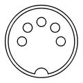
There are seven common patterns, with any number of pins from three to eight. Three different five-pin connectors exist, known as 180°, 240°, and domino/360°/270° after the angle of the arc swept between the first and last pin (see figures above). There are also two variations of the six-pin, seven-pin (one where the outer pins form 300° or 360° and one where they form 270°), and eight-pin (one where the outer pins form 270° and one where they form 262°) connectors.[5]
Of note, for eight-pin connectors,
DIN45326 defines the 8-pin 270° connector.
DIN41524 defines the 8-pin 262° connector, which was used as the video connector for the Commodore C64 computer.
There is some limited compatibility; for example, a three-pin connector will fit any 180° five-pin socket, engaging three of the pins and leaving the other two unconnected; and a three-pin or 180° five-pin connector will also fit a 270° seven-pin or either eight-pin socket. In addition to these connectors, there are also connectors with 10, 12, and 14 pins. Some high-range equipment used seven-pin connectors where the outer two carried digital system data:[6] if the connected equipment was incompatible, the outer two pins could be unscrewed from plugs so that they fitted into standard five-pin 180° sockets without data connections.
Screw-locking versions of this connector have also been used in instrumentation, process control, and professional audio.[7] In North America, this variant is often called a "small Tuchel" connector after one of the major manufacturers, now a division of Amphenol. Additional configurations up to 24 pins are also offered in the same shell size. A version with a bayonet locking ring was used on portable tape recorders, dictation machines, and lighting dimmers and controls through from the 1960s to the 1980s, an example being the microphone input connector and some others on the "Report" family of Uher tape recorders. The bayonet locking version is sometimes referred to by the trade name Preh. Belling Lee offered a version with a sprung-loaded collar which latched on insertion but required the collar to be pulled back to release the connector, similar to the LEMO B series connector. This connector was commonly referred to as the "Bleecon",[8] an example of its use being the Strand Tempus range of theatrical lighting dimmers and control desks.[8] A version with a pushbutton latch similar to that on an XLR cable mounted socket was also available. Female connectors with screw-locking, Bleecon, or bayonet latching features are compatible with standard DIN plugs.
Some manufacturers offered panel-mounted jacks with potential-free auxiliary contacts that would open if a plug were inserted.
Loudspeaker connector
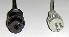
A polarised two-pin unshielded connector, designed for connecting a loudspeaker to a power amplifier (or other device; many of the earlier shoebox style tape recorders used them), is known as the DIN 41529 loudspeaker connector. It exists as a panel-mounting female version, and line-mounted male and female versions. The male version has a central flat pin, and circular pin mounted off-centre. The circular pin is connected to the positive line (red) while the spade is connected to the negative line (black).[9] The panel-mounting female version is available with or without an auxiliary contact that disconnects the internal speaker of the device if an external speaker connector is inserted. Most common is a three-hole female connector with one circular hole on either side of the spade hole, one of them with an aux contact and one without, which provides the option to leave the internal speaker connected by inserting the plug twisted by 180°.
It is now mainly found on older equipment, such as 16 mm movie projectors. The Becker radio found in many Mercedes-Benz automobiles uses this connector. The same connector is used on some LED lamps and halogen lamps to connect the bulb to the power supply. The two-pin DIN plug lacks the outer metal shell, so far less force is required to disconnect the plug accidentally. Worn two-pin speaker plugs often require only the slightest nudge to break contact. There are also three- and four-pin versions of this loudspeaker connector used for example by Bang & Olufsen.
Applications
Analog audio
The 3/180° and 5/180° connectors were originally standardized and widely used in European countries for interconnecting analog audio equipment. For example, a stereo tape recorder could connect to a stereo amplifier using the five pins for the four signal connections plus ground. The connectors on the cord are connected pin for pin, (pin 1 to pin 1, etc.). Pins on male connectors are numbered (from right to left, viewed from outside of the connector, with the five pins upwards, and facing them): 1–4–2–5–3. Holes on female connectors are also numbered 1-4-2-5-3, but from left to right (facing the holes). The three pins that make contact with a 3 pin DIN connector will have the same pin numbering both in the three-pin and the five-pin connector. A four-conductor cord wired in this way is sometimes called a DIN cord, a DIN lead or a DIN cable. For mono interconnections, the 3/180° plugs are sufficient. When a mono plug is inserted into a stereo socket, it mates with the left channel. For playback only interconnections, the 3/180° plugs are sufficient, with pin 1 and 3 used for the stereo channels and pin 2 as signal ground. Five-pin DIN inputs for record players and auxiliary signal sources commonly join pin 1 and 5 in order to be compatible both with the 3/180° and 5/180° pinouts. This generally works fine. However the join of pin 1 and 5 on adapters between DIN and RCA connectors can cause problems if used with a five-pin DIN connector tape connector on an amplifier or receiver, as it will join the left record with right playback signal. The other way around is usually not a problem as sending the right playback out of a tape recorder back in to the left record input usually imposes no problem in playback mode.
The signal levels are generally in the low range of line levels for playback/reproduction signals. The levels for recording can be considerable lower, more like microphone levels in some cases.
Some manufacturers, like Philips, Uher and others, did use the connector slightly different for tape recorders. Pin 2 (signal ground) were the same as others, and in playback mode pin 3 and 5 were used for left and right line level output as others. However in record mode all pins were active inputs, with pin 1 and 4 for low level signals like microphone levels, while pin 3 and 5 were used for line level signals. On all these recorders the output signals were only active in play mode, not in stop, record, rewind, fast forward or any other mode. The main benefits with this usage is that tape copying can be done with the regular pin-to-pin connected cables commonly used to connect tape recorders to amplifiers/receivers. An additional benefit is that several tape recorders can be connected in parallel, and can also be connected to an amplifier/receiver. Copying is done simply by pressing play on the playback recorder, rec on any recorders used for recording, and the amplifier/receiver is either switched off or set to the tape position. Recording of radio broadcasts or records is equally simple, just press record on any recorder and do not set any other recorder to playback mode. This eliminates the need for any switch boxes otherwise commonly used to connect more than one tape recorder to a single tape recorder connector on an amplifier/receiver. The drawbacks were that connecting any mono recorder with pin 1 joined to 4 and pin 5 joined to 3 (a common practice to make mono recorders record both channels in parallel and reproduce in both channels) would make all tape sounds mono. Also any tape recorder with three heads, used for monitoring while recording, needs an extra lead between the recorder and the amplifier to be able to monitor the recording through the amplifier and speakers. On Philips amplifiers/receivers and three head recorders that extra socket is labeled Monitor while the regular socket is labeled Tape. Another drawback is the possible confusion when interconnecting with other equipment, where a person sometimes would use a straight pin-to-pin cable and sometimes use a special "copying" cable with pin 1 swapped with pin 3 and pin 4 swapped with pin 5. Sometimes a person would also need to lower the signal to make a line output fit a microphone level input.
This interface was rare outside products for the European market, and has progressively disappeared on new equipment, both in Europe and worldwide, since the 1980s, in favour of RCA connectors.
| Application | Connector | Pin function | |||||
|---|---|---|---|---|---|---|---|
| 1 | 4 | 2 | 5 | 3 | |||
| Amplifier | Monophonic | 5/180° |
Audio out | Screen/return | Audio in | ||
| Stereophonic | Left out | Right out | Right in | Left in | |||
| Tape recorder | Monophonic | Audio in | Audio out | ||||
| Stereophonic | Left in | Right in | Right out | Left out | |||
| Common colors on DIN-4*RCA adapters | white | red | yellow | black | |||
| Common colors on DIN-2*RCA adapters | (sometimes joined with pin 5) | red | white | ||||
Other uses
The 5/180° connectors are commonly used for:
- SYNC or MIDI interface for electronic musical instruments
- Peripherals or power connectors for personal computers from the 1980s
- Audio in the original HME wireless communicators (It is the headset connector for inbound and outbound audio for drive-through restaurants.)
- Controlling tilt of UMTS antennas (Antenna Interface Standards Group)[10]
- Connecting two controllers for radio controlled model aircraft together for training purposes.
The DIN connector saw several other uses apart from audio. It was particularly popular as a connector for various home computers and video game consoles.
Analogue theatrical lighting control (pre-dating the more recent digital control protocols such as DMX) commonly used the 8-pin (45°) DIN connector, six of the pins being 0–10V control signals for six separate dimmer circuits, and the other two a 0V reference and a DC source for powering simple circuitry in rudimentary lighting desks. Pinouts vary between manufacturers: Zero 88, Anytronics, Lightprocessor and Strand have the control signals on pins 1–6, 0V on pin 8 and power on pin 7 and Pulsar and Clay Paky have power on pin 1, 0V on pin 2 and channel outputs on pins 3 to 8. The polarity of the power supply and control signals relative to ground also varies, with Strand having negative voltages, but most other brands having positive voltages.[11]
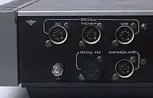
In the Soviet Union, three-pin and five-pin DIN connectors named ОНЦ-ВГ (Latin: ONC-VG), could be seen on many pieces of equipment, as well as factory-made audio equipment. Radio amateurs and small cooperatives quickly discovered these reliable connectors and began to put them into almost every low frequency signal device, often with non-standard pin usage. Versions other than three- or five-pin were very rare in the USSR and very hard to buy. Four-pin DIN connectors, for example, were never seen on any device or in stores.
See also
| Wikimedia Commons has media related to DIN connectors. |
References
- Deutsches Institut für Normung (March 1974). "DIN 41524:1974-03: Dreipolige und fünfpolige Steckverbinder für Rundfunk- und verwandte Geräte". Beuth Verlag GmbH. Retrieved 2017-04-01.
- IEC 60130-9: "Connectors for frequencies below 3 MHz — Part 9: Circular connectors for radio and associated sound equipment." International Electrotechnical Commission, Geneva, 2011.
- I have a Philips tape recorder which has a 'domino' headphone socket, the headphone plug has a cut-out in the body thus allowing the external speakers to remain active or not as required.
- "Why are domino plugs reversible". stardot.org.uk. Retrieved 2017-05-10.
- Markström, Håkan (2017-11-18). "Kablar" (in Swedish). Retrieved 2019-04-02.
- "Sounds Heavenly - Help and Advice". Retrieved 2009-03-19.
- IEC 60268-11
- "Bleecon". www.blue-room.org.uk. Retrieved 2017-05-09.
- Carter, Simon (2010). "DIN Connectors". Electronics 2000. Retrieved 27 March 2010.
- "AISG Website". 5 March 2009. Retrieved 8 May 2009.
AISG (13 June 2006). "Control interface for antenna line devices" (PDF). Archived from the original (PDF) on 20 July 2011. Retrieved 8 May 2009. - "0 to 10V Analog Control Protocol". Retrieved 2017-05-10.
- DIN Connectors
- IEC 60574-3: Audiovisual, video and television equipment and systems — Part 3: Specification for connectors for the interconnection of equipment in audiovisual systems.