Free body diagram
A free body diagram consists of a diagrammatic representation of a single body or a subsystem of bodies isolated from its surroundings showing all the forces acting on it In physics and engineering, a free body diagram (force diagram,[1] or FBD) is a graphical illustration used to visualize the applied forces, moments, and resulting reactions on a body in a given condition. They depict a body or connected bodies with all the applied forces and moments, and reactions, which act on the body(ies). The body may consist of multiple internal members (such as a truss), or be a compact body (such as a beam). A series of free bodies and other diagrams may be necessary to solve complex problems.
Purpose
Free body diagrams are used to visualize the forces and moments applied to a body and to calculate the resulting reactions in many types of mechanics problems. These diagrams are frequently used both to determine the loading of individual structural components and to calculate internal forces within the structure, and they are utilized across most engineering disciplines from Biomechanics to Structural Engineering.[2][3] In the educational environment, learning to draw a free body diagram is an important step to understanding certain topics in physics, such as statics, dynamics and other forms of classical mechanics.
Features
A free body diagram is not meant to be a scaled drawing. It is a diagram that is modified as the problem is solved. There is an art and flexibility to the process. The iconography of a free body diagram, not only how it is drawn but also how it is interpreted, depends upon how a body is modeled.[4]
Free body diagrams consist of:
- A simplified version of the body (often a dot or a box)
- Forces shown as straight arrows pointing in the direction they act on the body
- Moments shown as curved arrows pointing in the direction they act on the body
- A coordinate system
- Frequently reactions to applied forces are shown with hash marks through the stem of the arrow
The number of forces and moments shown in a free body diagram depends on the specific problem and the assumptions made; common assumptions are neglecting air resistance and friction, and assuming rigid bodies. In statics all forces and moments must balance to zero; the physical interpretation of this is that if the forces and moments do not sum to zero the body is accelerating and the principles of statics do not apply. In dynamics the resultant forces and moments can be non-zero.
Free body diagrams may not represent an entire physical body. Using what is known as a "cut", only portions of a body are selected for modeling. This technique exposes internal forces, making them external, therefore allowing analysis. This technique is often used several times, iteratively, to peel back forces acting on a physical body. For example, a gymnast performing the iron cross: analyzing the ropes and the person lets you know the total force (body weight, neglecting rope weight, breezes, buoyancy, electrostatics, relativity, rotation of the earth, etc.). Then cut the person out and only show one rope; you get force direction. Then only look at the person; now you can get hand forces. Now only look at the arm to get the shoulder forces and moments, and on and on until the component you intend to analyze is exposed.
Modeling the body
A body may be modeled in three ways:
- a particle. This model may be used when any rotational effects are zero or have no interest even though the body itself may be extended. The body may be represented by a small symbolic blob and the diagram reduces to a set of concurrent arrows. A force on a particle is a bound vector.
- rigid extended. Stresses and strains are of no interest but turning effects are. A force arrow should lie along the line of force, but where along the line is irrelevant. A force on an extended rigid body is a sliding vector.
- non-rigid extended. The point of application of a force becomes crucial and has to be indicated on the diagram. A force on a non-rigid body is a bound vector. Some use the tail of the arrow to indicate the point of application. Others use the tip.
Example: A body in free fall
Consider a body in free fall in a uniform gravitational field. The body may be
- a particle. It is enough to show a single vertically downward pointing arrow attached to a blob.
- rigid extended. A single arrow suffices to represent the weight W even though calm gravitational attraction acts on every particle of the body.
- non-rigid extended. In non-rigid analysis, it would be an error to associate a single point of application with the gravitational force.
What is included
An FBD represents the body of interest and the external forces on it.
- The body: This is usually sketched in a schematic way depending on the body—particle/extended, rigid/non-rigid—and on what questions are to be answered. Thus if rotation of the body and torque is in consideration, an indication of size and shape of the body is needed. For example, the brake dive of a motorcycle cannot be found from a single point, and a sketch with finite dimensions is required.
- The external forces: These are indicated by labelled arrows. In a fully solved problem, a force arrow is capable of indicating
Typically, however, a provisional free body sketch is drawn before all these things are known. After all, the purpose of the diagram is to help to determine magnitude, direction, and point of application of the external loads. Thus when a force arrow is originally drawn, its length may not be meant to indicate the unknown magnitude. Its line may not correspond to the exact line of action. Even its direction may turn out to be wrong. Very often the original direction of the arrow may be directly opposite to the true direction. External forces known to be small that are known to have negligible effect on the result of the analysis are sometimes omitted, but only after careful consideration or after other analysis proving it (e.g. buoyancy forces of the air in the analysis of a chair, or atmospheric pressure on the analysis of a frying pan).
The external forces acting on the object include friction, gravity, normal force, drag, tension, or a human force due to pushing or pulling. When in a non-inertial reference frame (see coordinate system, below), fictitious forces, such as centrifugal pseudoforce are appropriate.
A coordinate system is sometimes included, and is chosen according to convenience (or advantage). Savvy selection of coordinate frame may make defining the vectors simpler when writing the equations of motion. The x direction might be chosen to point down the ramp in an inclined plane problem, for example. In that case the friction force has only an x component, and the normal force has only a y component. The force of gravity will still have components in both the x and y directions: mgsin(θ) in the x and mgcos(θ) in the y, where θ is the angle between the ramp and the horizontal.
Exclusions
There are some things that a free body diagram explicitly excludes. Although other sketches that include these things may be helpful in visualizing a problem, a proper free body diagram should not show:
- Bodies other than the free body.
- Constraints.
- (The body is not free from constraints; the constraints have just been replaced by the forces and moments that they exert on the body.)
- Forces exerted by the free body.
- (A diagram showing the forces exerted both on and by a body is likely to be confusing since all the forces will cancel out. By Newton's 3rd law if body A exerts a force on body B then B exerts an equal and opposite force on A. This should not be confused with the equal and opposite forces that are necessary to hold a body in equilibrium.)
- Internal forces.
- (For example, if an entire truss is being analyzed, the forces between the individual truss members are not included.)
- Velocity or acceleration vectors.
Analysis
A free body diagram is analyzed by summing all of the forces, often accomplished by summing the forces in each of the axis directions. When the net force is zero, the body must be at rest or must be moving at a constant velocity (constant speed and direction), by Newton's first law. If the net force is not zero, then the body is accelerating in that direction according to Newton's second law.
Angled forces
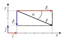
Determining the sum of the forces is straightforward if all they are aligned with the coordinate frame's axes, but it is somewhat more complex if some forces are not aligned. It is often convenient to analyze the components of the forces, in which case the symbols ΣFx and ΣFy are used instead of ΣF. Forces that point at an angle to the diagram's coordinate axis can be broken down into two parts (or three, for three dimensional problems)—each part being directed along one of the axes—horizontally (Fx) and vertically (Fy).
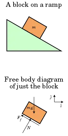
Example: A block on an inclined plane
A simple free body diagram, shown above, of a block on a ramp illustrates this.
- All external supports and structures have been replaced by the forces they generate. These include:
- mg: the product of the mass of the block and the constant of gravitation acceleration: its weight.
- N: the normal force of the ramp.
- Ff: the friction force of the ramp.
- The force vectors show direction and point of application and are labeled with their magnitude.
- It contains a coordinate system that can be used when describing the vectors.
Some care is needed in interpreting the diagram.
- The normal force has been shown to act at the midpoint of the base, but if the block is in static equilibrium its true location is directly below the center of mass, where the weight acts, because that is necessary to compensate for the moment of the friction.
- Unlike the weight and normal force, which are expected to act at the tip of the arrow, the friction force is a sliding vector and thus the point of application is not relevant, and the friction acts along the whole base.
Kinetic diagram
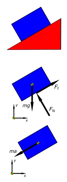
In dynamics a kinetic diagram is a pictorial device used in analyzing mechanics problems when there is determined to be a net force and/or moment acting on a body. They are related to and often used with free body diagrams, but depict only the net force and moment rather than all of the forces being considered.
Kinetic diagrams are not required to solve dynamics problems; their use in teaching dynamics is argued against by some[5] in favor of other methods that they view as simpler. They appear in some dynamics texts[6] but are absent in others.[7]
See also
| Wikimedia Commons has media related to Free body diagrams. |
| Wikimedia Commons has media related to Vector force diagrams. |
- Classical Mechanics
- Force field analysis – applications of force diagram in social science
- Kinematic diagram
- Physics
- Shear and moment diagrams
References
- "Force Diagrams (Free-body Diagrams)". Western Kentucky University. Retrieved 2011-03-17.
- Ruina, Andy; Pratap, Rudra (2010). Introduction to Statics and Dynamics (PDF). Oxford University Press. pp. 79–105. Retrieved 2006-08-04.
- Hibbeler, R.C. (2007). Engineering Mechanics: Statics & Dynamics (11th ed.). Pearson Prentice Hall. pp. 83–86. ISBN 978-0-13-221509-1.
- Puri, Avinash (1996). "The Art of Free-body Diagrams". Physics Education. 31 (3): 155. Bibcode:1996PhyEd..31..155P. doi:10.1088/0031-9120/31/3/015.
- Kraige, L. Glenn (16 June 2002). "The Role Of The Kinetic Diagram In The Teaching Of Introductory Rigid Body Dynamics Past, Present, And Future": 7.1182.1–7.1182.11. Cite journal requires
|journal=(help) - "Stress and Dynamics" (PDF). Retrieved August 5, 2015.
- Ruina, Andy; Pratap, Rudra (2002). Introduction to Statics and Dynamics. Oxford University Press. Retrieved September 4, 2019.
Notes
- The line of action is important where moment matters