Friction extrusion
Friction extrusion is a thermo-mechanical process that can be used to form fully consolidated wire, rods, tubes, or other non-circular metal shapes directly from a variety of precursor charges including metal powder, flake, machining waste (chips or swarf) or solid billet. The process imparts unique, and potentially, highly desirable microstructures to the resulting products. Friction extrusion was invented at The Welding Institute in the UK and patented in 1991. It was originally intended primarily as a method for production of homogenous microstructures and particle distributions in metal matrix composite materials.[1]
Description of the Process and Essential Process Variables
As in conventional extrusion processes, in friction extrusion, a shape change is enforced on the charge by forcing its passage through a die. However, friction extrusion differs from conventional extrusion in several key ways. Critically, in the friction extrusion process, the extrusion charge (billet or other precursor) rotates relative to the extrusion die. In addition, similar to conventional extrusion, an extrusion force is applied so as to push the charge against the die. In practice either the die or the charge may rotate or they may be counter-rotating. The relative rotary motion between the charge and the die has several significant effects on the process. First, the relative motion in the plane of rotation leads to large shear stresses, hence, plastic deformation in the layer of charge in contact with and near the die. This plastic deformation is dissipated by recovery and recrystallization processes leading to substantial heating of the deforming charge. Because of the deformation heating, friction extrusion does not generally require preheating of the charge by auxiliary means potentially resulting in a more energy efficient process. Second, the substantial level of plastic deformation in the region of relative rotary motion can promote solid state welding of powders or other finely divided precursors, such as flakes and chips, effectively consolidating the charge (friction consolidation) prior to extrusion.[2] Scrolled features on the face of the die aid material flow into the extrusion orifice which can lead to order of magnitude reduction in extrusion force compared to conventional extrusions of equivalent cross section.[3] Third, the combined effects of elevated temperature and large levels of deformation normally lead the extrudate to have a relatively fine, equiaxed, grain structure which results from recrystallization after the conclusion of deformation: desirable crystallographic textures may also be created by the process and formation of nanocomposite structures are also possible.[4]
Based on the foregoing, it can be said that the essential controlled parameters in friction extrusion are typically:
- The die rotation rate.
- The die geometry.
- The extrusion force normal to the die face or, the rate of die advance into the charge.
The corresponding response parameters include:
- The required torque and power.
- The extrusion temperature.
- The extrusion rate in force controlled extrusion or the extrusion force in rate controlled extrusion.
- The extrudate microstructure and properties.
Friction Extrusion Equipment
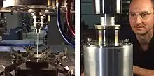
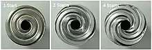
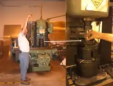
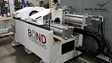
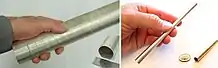
In principle, friction extrusion can be performed on any machine which can produce the required rotary and linear motions between the die and charge. Examples include machines built for friction stir welding, milling machines modified to accommodate the extrusion forces, and purpose built friction extrusion equipment such as the shear assisted processing and extrusion (ShAPE™) machine at the Pacific Northwest National Laboratory. Figures 1-3 show examples of friction extrusion equipment and extruded products. Figure 4 shows typical friction extrusion dies designed for production of wire, rod and tube. Dies are rotated in the direction which enhances material flow toward the extrusion orifice during the process.
Strain in Friction Extrusion
In conventional extrusion, the strain imparted to the charge is loosely defined by the extrusion ratio.[5] The extrusion ratio is simply the cross-sectional area of the extrusion billet, A0, divided by the cross sectional area of the extrudate, Af. The extrusion strain is then e=ln(A0/Af).
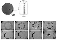
In friction extrusion there is an additional strain component which will arise from the shearing motion of the rotating die as it contacts the charge. The strain produced by the rotation of the die results in redundant work as it does not accomplish a shape change. In order to investigate the strain due to shearing, studies have been performed with marker materials embedded in the material to be extruded.[6] After extrusion, these materials are detected by metallographic methods and provide insight regarding the way in which material flows during the extrusion process. Figure 5 shows an example of how the amount of shear strain changes with changing ratios of extrusion rate to die rotation rate. In the limit of very high extrusion rates, the friction extrusion process closely mimics the conventional extrusion process with respect to strain levels.
Typical microstructure resulting from friction extrusion
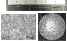
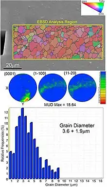
Figure 6 shows the cross section and microstructure of a titanium wire produced by friction extrusion of Ti-6-4 powder. Notably, the cross section is fully consolidated and the transformed b microstructure indicates that extrusion likely occurred near 1000 °C (above the beta transus for the alloy). Figure 7 shows grain size and crystallographic orientation typical of thin walled tubing extruded from AZ91 melt spun flake.[7] Grains are refined to less than 5 mm and orientation of the (0001) planes are off-normal due to the rotational shear component. Figure 8 shows examples of friction extruded magnesium alloy tubes. Friction consolidation has also been used to refine grain size and preferentially orient texture in functional materials such as bismuth-telluride thermoelectrics [8] and iron-silicon magnets.[9] Examples of the effect of friction extrusion of microstructure have been reported for AZ31,[10][11][12] various aluminum alloys [13][14][15][16] and pure copper.[17]
Potential of Friction Extrusion for Commercialization
- Creep resistant steel piping.
- Lightweight magnesium and aluminum structures.
- Materials with enhanced thermal properties.
- Recycling of aluminum machining waste and swarf.
- Nanocomposite functional materials.
Advantages and Disadvantages Relative to Conventional Extrusion
Advantages
- Potential for significantly lower power consumption and extrusion force compared to conventional extrusion due to rotational shear generating the necessary process heat and scroll features aiding material flow into the extrusion orifice.[3]
- Friction extrusion is capable of refining microstructure from powder/flake/chip (bottom-up) and solid billets (top-down).[2][3][7][18]
- Enables extrusion of materials, such as Mg2Si which cannot be readily extruded by conventional means.[19]
- As a solid-phase process, friction extrusion can be done at low temperature thereby retaining nanoscale second phases and particles present in precursor material. Enables fabrication of bulk nanocomposite materials.[4][7][19][20]
- Enables enhanced bulk properties, such as energy absorption in magnesium alloys.[19]
Disadvantages
- Extrusion rates competitive with conventional extrusion processes have yet to be demonstrated.
- Uniformity of microstructure and material properties are difficult to obtain in plane perpendicular to extrusion direction because the imposed strain is non-uniform.[6]
- Full range of process scalability has not been assessed.
References
- “Forming metallic composite materials by urging base materials together under shear” US patent #5262123 A, Inventors: W. Thomas, E. Nicholas, and S. Jones, Original Assignee: The Welding Institute.
- Tang, W.; Reynolds, A.P. (2010). "Production of wire via friction extrusion of aluminum alloy machining chips". Journal of Materials Processing Technology. 210 (15): 2231–2237. doi:10.1016/j.jmatprotec.2010.08.010.
- "Scaled-up fabrication of thin-walled magnesium ZK60 tubing using shear assisted processing and extrusion (ShAPE™)", S. Whalen, V. Joshi, N. Overman, D. Caldwell, C. Lavender, T. Skszek, Magnesium Technology, 315-321, 2017.
- “Dispersoid distribution and microstructure in Fe-Cr-Al ferritic oxide dispersion-strengthened alloy prepared by friction consolidation”, D. Catalini, D. Kaoumi, AP Reynolds, G. Grant, Metallurgical and Materials Transactions A, v. 46, no. 10, pp. 4730–4739, 2015.
- “Manufacturing Processes for Engineering Materials, 5th ed.”, S. Kalpakjian and S. R. Schmid, ISBN 0132272717, pp. 307-314, 2008.
- “Strain and texture in friction extrusion of aluminum wire”, X. Li, W. Tang, AP Reynolds, WA Tayon, CA Brice, Journal of Materials Processing Technology, v. 229 ,pp. 191-198, 2016.
- “Microstructural evolution of rapidly solidified AZ91E flake consolidated by shear assisted processing and extrusion (ShAPE™)”, N. Overman, S. Whalen, M. Olszta, K. Kruska, J. Darsell, V. Joshi, X. Jiang, K. Mattlin, E. Stephens, T. Clark, S. Mathaudhu, Materials Science and Engineering A, 701, pp. 56-68, 2017.
- “Friction consolidation processing of n-type bismuth-telluride thermoelectric material”, S. Whalen, S. Jana, D. Catalini, N. Overman, J. Sharp, Journal of Electronic Materials, 45(7), pp. 3390-3399, 2016
- “Friction consolidation of gas-atomized Fe-Si powders for soft magnetic applications”, X. Jiang, S. Whalen, J. Darsell, S. Mathaudhu, N. Overman, Materials Characterization, v. 123, pp. 166-172, 2017
- J. Milner, F. Abu-Farha, “https://link.springer.com/chapter/10.1007/978-3-319-48231-6_50 Microstructural evolution and its relationship to the mechanical properties of Mg AZ31B friction stir back extruded tubes]”, Magnesium Technology, pp. 263-268, 2014
- “A numerical model for Wire integrity prediction in Friction Stir Extrusion of magnesium alloys”, D. Baffari, G. Buffa, L. Fratini, Journal of Materials Processing Technology,pp. 1-10, 2017
- “AZ31 magnesium alloy recycling through friction stir extrusion process”, G. Buffa, D. Campanella, L. Fratini, F. Micari, International Journal of Material Forming, 1-6, 2015
- “A preliminary study on the feasibility of friction stir back extrusion”, F. Abu-Farha, Scripta Materialia, 66, pp. 615-618, 2012.
- "Production of wire from AA7277 aluminum chips via friction-stir extrusion (FSE)", R. Behnagh, R. Mahdavinejad, A. Yivari, M. Abdollah, M. Narvan, Metallurgical and Materials Transactions B, 45:4, pp. 1484–1489, 2014
- "Microstructure evolutions and mechanical properties of tubular aluminum produced by friction stir back extrusion", M. Khorrami, M. Movahedi, Materials and Design, 65, pp. 74-79, 2015
- "Direct solid-state conversion of recyclable metals and alloys", V. Manchiraju, Final Technical Report DE-EE0003458, Oak Ridge National Laboratory, 2012
- "Microstructural characterization of pure copper tubes produced by a novel method – friction stir back extrusion", I. Dinaharan, R. Sathiskumar, S. Vijay, N. Murugan, Procedia Materials Science, 5, pp. 1502–1508, 2015
- Baffari, Dario; Reynolds, Anthony P.; Li, Xiao; Fratini, Livan (2017). "Influence of processing parameters and initial temper on Friction Stir Extrusion of 2050 aluminum alloy". Journal of Manufacturing Processes. 28: 319–325. doi:10.1016/j.jmapro.2017.06.013.
- "High shear deformation to produce high strength and energy absorption in Mg alloys", V. Joshi, S. Jana, D. Li, H. Garmestani, E. Nyberg, C. Lavender, pp. 83-88, Magnesium Technology, 2014
- Catalini, David; Kaoumi, Djamel; Reynolds, Anthony P.; Grant, Glenn J. (2013). "Friction Consolidation of MA956 powder". Journal of Nuclear Materials. 442 (1–3): S112–S118. Bibcode:2013JNuM..442S.112C. doi:10.1016/j.jnucmat.2012.11.054.