Gimbal
A gimbal is a pivoted support that allows the rotation of an object about a single axis. A set of three gimbals, one mounted on the other with orthogonal pivot axes, may be used to allow an object mounted on the innermost gimbal to remain independent of the rotation of its support (e.g. vertical in the first animation). For example, on a ship, the gyroscopes, shipboard compasses, stoves, and even drink holders typically use gimbals to keep them upright with respect to the horizon despite the ship's pitching and rolling.
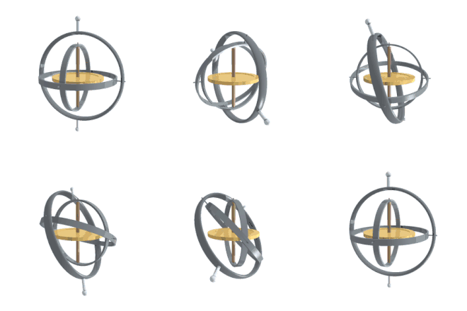
The gimbal suspension used for mounting compasses and the like is sometimes called a Cardan suspension after Italian mathematician and physicist Gerolamo Cardano (1501–1576) who described it in detail. However, Cardano did not invent the gimbal, nor did he claim to. The device has been known since antiquity, first described in the 3rd c. BC by Philo of Byzantium, although some modern authors support the view that it may not have a single identifiable inventor.[1][2]
History

The gimbal was first described by the Greek inventor Philo of Byzantium (280–220 BC).[3][4][5][6] Philo described an eight-sided ink pot with an opening on each side, which can be turned so that while any face is on top, a pen can be dipped and inked — yet the ink never runs out through the holes of the other sides. This was done by the suspension of the inkwell at the center, which was mounted on a series of concentric metal rings so that it remained stationary no matter which way the pot is turned.[3]
In Ancient China, the Han Dynasty (202 BC – 220 AD) inventor and mechanical engineer Ding Huan created a gimbal incense burner around 180 AD.[3][7][8] There is a hint in the writing of the earlier Sima Xiangru (179–117 BC) that the gimbal existed in China since the 2nd century BC.[9] There is mention during the Liang Dynasty (502–557) that gimbals were used for hinges of doors and windows, while an artisan once presented a portable warming stove to Empress Wu Zetian (r. 690–705) which employed gimbals.[10] Extant specimens of Chinese gimbals used for incense burners date to the early Tang Dynasty (618–907), and were part of the silver-smithing tradition in China.[11]
The authenticity of Philo's description of a cardan suspension has been doubted by some authors on the ground that the part of Philo's Pneumatica which describes the use of the gimbal survived only in an Arabic translation of the early 9th century.[3] Thus, as late as 1965, the sinologist Joseph Needham suspected Arab interpolation.[12] However, Carra de Vaux, author of the French translation which still provides the basis for modern scholars,[13] regards the Pneumatics as essentially genuine.[14] The historian of technology George Sarton (1959) also asserts that it is safe to assume the Arabic version is a faithful copying of Philo's original, and credits Philon explicitly with the invention.[15] So does his colleague Michael Lewis (2001).[16] In fact, research by the latter scholar (1997) demonstrates that the Arab copy contains sequences of Greek letters which fell out of use after the 1st century, thereby strengthening the case that it is a faithful copy of the Hellenistic original,[17] a view recently also shared by the classicist Andrew Wilson (2002).[18]
The ancient Roman author Athenaeus Mechanicus, writing during the reign of Augustus (30 BC–14 AD), described the military use of a gimbal-like mechanism, calling it "little ape" (pithêkion). When preparing to attack coastal towns from the sea-side, military engineers used to yoke merchant-ships together to take the siege machines up to the walls. But to prevent the shipborne machinery from rolling around the deck in heavy seas, Athenaeus advises that "you must fix the pithêkion on the platform attached to the merchant-ships in the middle, so that the machine stays upright in any angle".[19]
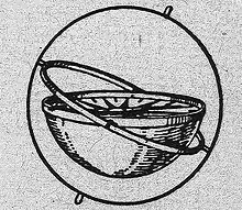
After antiquity, gimbals remained widely known in the Near East. In the Latin West, reference to the device appeared again in the 9th century recipe book called the Little Key of Painting Mappae clavicula.[20] The French inventor Villard de Honnecourt depicts a set of gimbals in his famous sketchbook (see right). In the early modern period, dry compasses were suspended in gimbals.
Applications
Inertial navigation
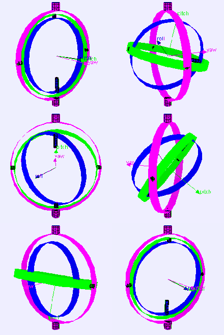
In inertial navigation, as applied to ships and submarines, a minimum of three gimbals are needed to allow an inertial navigation system (stable table) to remain fixed in inertial space, compensating for changes in the ship's yaw, pitch, and roll. In this application, the inertial measurement unit (IMU) is equipped with three orthogonally mounted gyros to sense rotation about all axes in three-dimensional space. The gyro outputs are kept to a null through drive motors on each gimbal axis, to maintain the orientation of the IMU. To accomplish this, the gyro error signals are passed through "resolvers" mounted on the three gimbals, roll, pitch and yaw. These resolvers perform an automatic matrix transformation according to each gimbal angle, so that the required torques are delivered to the appropriate gimbal axis. The yaw torques must be resolved by roll and pitch transformations. The gimbal angle is never measured. Similar sensing platforms are used on aircraft.
In inertial navigation systems, gimbal lock may occur when vehicle rotation causes two of the three gimbal rings to align with their pivot axes in a single plane. When this occurs, it is no longer possible to maintain the sensing platform's orientation.
Rocket engines
In spacecraft propulsion, rocket engines are generally mounted on a pair of gimbals to allow a single engine to vector thrust about both the pitch and yaw axes; or sometimes just one axis is provided per engine. To control roll, twin engines with differential pitch or yaw control signals are used to provide torque about the vehicle's roll axis.
The word "gimbal" began as a noun. Most modern dictionaries continue to list it as such. Lacking a convenient term to describe the swinging movement of a rocket engine, engineers began also using the word "gimbal" as a verb. When a thrust chamber is swung by an attached actuator, the movement is referred to as "gimballed" or "gimballing". Official rocket documentation reflects this usage.
Photography and imaging
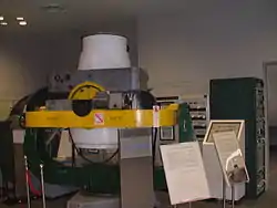
Gimbals are also used to mount everything from small camera lenses to large photographic telescopes.
In portable photography equipment, single-axis gimbal heads are used in order to allow a balanced movement for camera and lenses.[21] This proves useful in wildlife photography as well as in any other case where very long and heavy telephoto lenses are adopted: a gimbal head rotates a lens around its center of gravity, thus allowing for easy and smooth manipulation while tracking moving subjects.
Very large gimbal mounts in the form 2 or 3 axis altitude-altitude mounts[22] are used in satellite photography for tracking purposes.
Gyrostabilized gimbals which house multiple sensors are also used for airborne surveillance applications including airborne law enforcement, pipe and power line inspection, mapping, and ISR (intelligence, surveillance, and reconnaissance). Sensors include thermal imaging, daylight, low light cameras as well as laser range finder, and illuminators.[23]
Gimbal systems are also used in scientific optics equipment. For example, they are used to rotate a material sample along an axis to study their angular dependence of optical properties.[24]
Film and video
Handheld 3-axis gimbals are used in stabilization systems designed to give the camera operator the independence of handheld shooting without camera vibration or shake. There are two versions of such stabilization systems: mechanical and motorized.
Mechanical gimbals have the sled, which includes the top stage where the camera is attached, the post which in most models can be extended, with the monitor and batteries at the bottom to counterbalance the camera weight. This is how the Steadicam stays upright, by simply making the bottom slightly heavier than the top, pivoting at the gimbal. This leaves the center of gravity of the whole rig, however heavy it may be, exactly at the operator's fingertip, allowing deft and finite control of the whole system with the lightest of touches on the gimbal.
Powered by three brushless motors, motorized gimbals have the ability to keep the camera level on all axes as the camera operator moves the camera. An inertial measurement unit (IMU) responds to movement and utilizes its three separate motors to stabilize the camera. With the guidance of algorithms, the stabilizer is able to notice the difference between deliberate movement such as pans and tracking shots from unwanted shake. This allows the camera to seem as if it is floating through the air, an effect achieved by a Steadicam in the past. Gimbals can be mounted to cars and other vehicles such as drones, where vibrations or other unexpected movements would make tripods or other camera mounts unacceptable.
Marine chronometers
The rate of a mechanical marine chronometer is sensitive to its orientation. Because of this, chronometers were normally mounted on gimbals, in order to isolate them from the rocking motions of a ship at sea.
Gimbal lock
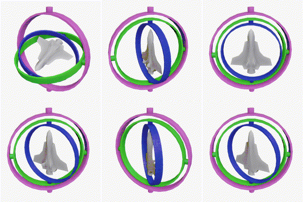
Gimbal lock is the loss of one degree of freedom in a three-dimensional, three-gimbal mechanism that occurs when the axes of two of the three gimbals are driven into a parallel configuration, "locking" the system into rotation in a degenerate two-dimensional space.
The word lock is misleading: no gimbal is restrained. All three gimbals can still rotate freely about their respective axes of suspension. Nevertheless, because of the parallel orientation of two of the gimbals' axes there is no gimbal available to accommodate rotation about one axis.
References
- Needham, Joseph. (1986). Science and Civilization in China: Volume 4, Physics and Physical Technology; Part 2, Mechanical Engineering. Taipei: Caves Books Ltd. Page 229.
- Francis C. Moon, The Machines of Leonardo da Vinci and Franz Reuleaux: Kinematics of Machines from the Renaissance to the 20th century, p.314, Springer, 2007 ISBN 1-4020-5598-6.
- Sarton, George (1959). A History of Science: Hellenistic Science and Culture in the Last Three centuries B.C. Cambridge: Harvard University Press. pp. 349–350.
- Carter, Ernest Frank (1967). Dictionary of Inventions and Discoveries. Philosophical Library. p. 74.
- Seherr-Thoss, Hans-Christoph; Schmelz, Friedrich; Aucktor, Erich (2006). Universal Joints and Driveshafts: Analysis, Design, Applications. Springer. p. 1. ISBN 978-3-540-30169-1.
- Krebs, Robert E.; Krebs, Carolyn A. (2003). Groundbreaking Scientific Experiments, Inventions, and Discoveries of the Ancient World. Greenwood Press. p. 216. ISBN 978-0-313-31342-4.
- Needham, Joseph. (1986). Science and Civilization in China: Volume 4, Physics and Physical Technology; Part 2, Mechanical Engineering. Taipei: Caves Books Ltd. p.233.
- Handler, Sarah (2001). Austere Luminosity of Chinese Classical Furniture. University of California Press (published October 1, 2001). p. 308. ISBN 978-0520214842.
- Needham, Joseph. (1986). Science and Civilization in China: Volume 4, Physics and Physical Technology; Part 2, Mechanical Engineering. Taipei: Caves Books Ltd. pp.233–234.
- Needham, Joseph. (1986). Science and Civilization in China: Volume 4, Physics and Physical Technology; Part 2, Mechanical Engineering. Taipei: Caves Books Ltd. p.234.
- Needham, Joseph. (1986). Science and Civilization in China: Volume 4, Physics and Physical Technology; Part 2, Mechanical Engineering. Taipei: Caves Books Ltd. pp.234–235.
- Needham, Joseph. (1986). Science and Civilization in China: Volume 4, Physics and Physical Technology; Part 2, Mechanical Engineering. Taipei: Caves Books Ltd. p.236.
- Hill, D. R. (1977). History of Technology. Part II. p. 75.
- Carra de Vaux: "Le livre des appareils pneumatiques et des machines hydrauliques de Philon de Byzance d'après les versions d'Oxford et de Constantinople", Académie des Inscriptions et des Belles Artes: notice et extraits des mss. de la Bibliothèque nationale, Paris 38 (1903), pp.27-235
- Sarton, George. (1959). A History of Science: Hellenistic Science and Culture in the Last Three centuries B.C. New York: The Norton Library, Norton & Company Inc. SBN 393005267. pp.343–350.
- Lewis, M. J. T. (2001). Surveying Instruments of Greece and Rome. Cambridge University Press. p. 76 at Fn. 45. ISBN 978-0-521-79297-4.
- Lewis, M. J. T. (1997). Millstone and Hammer: the Origins of Water Power. pp. 26–36.
- Wilson, Andrew (2002). "Machines, Power and the Ancient Economy". The Journal of Roman Studies. 92 (7): 1–32. doi:10.1017/S0075435800032135.
- Athenaeus Mechanicus, "On Machines" ("Peri Mēchanēmatōn"), 32.1-33.3
- Needham, Joseph. (1986). Science and Civilization in China: Volume 4, Physics and Physical Technology; Part 2, Mechanical Engineering. Taipei: Caves Books Ltd. pp.229, 231.
- "3-Axis Handheld GoPro Gimbals". gimbalreview.com. GimbalReview. 2017. Retrieved 7 May 2017.
- "Article". Soviet Journal of Optical Technology. Optical Society of America, American Institute of Physics. 43 (3): 119. 1976.
- Dietsch, Roy (2013). Airborne Gimbal Camera – Interface Guide.
- Bihari, Nupur; Dash, Smruti Prasad; Dhankani, Karankumar C.; Pearce, Joshua M. (2018-12-01). "3-D printable open source dual axis gimbal system for optoelectronic measurements" (PDF). Mechatronics. 56: 175–187. doi:10.1016/j.mechatronics.2018.07.005. ISSN 0957-4158.
External links
 Media related to Gimbals at Wikimedia Commons