Grid-leak detector
A grid leak detector is an electronic circuit that demodulates an amplitude modulated alternating current and amplifies the recovered modulating voltage. The circuit utilizes the non-linear cathode to control grid conduction characteristic and the amplification factor of a vacuum tube.[1][2] Invented by Lee De Forest around 1912, it was used as the detector (demodulator) in the first vacuum tube radio receivers until the 1930s.
History
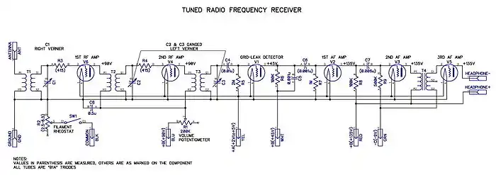
Early applications of triode tubes (Audions) as detectors usually did not include a resistor in the grid circuit.[4] First use of a resistance to discharge the grid condenser in a vacuum tube detector circuit may have been by Sewall Cabot in 1906. Cabot wrote that he made a pencil mark to discharge the grid condenser, after finding that touching the grid terminal of the tube would cause the detector to resume operation after having stopped.[5] Edwin H. Armstrong, in 1915, describes the use of "a resistance of several hundred thousand ohms placed across the grid condenser" for the purpose of discharging the grid condenser.[6] The heyday for grid leak detectors was the 1920s, when battery operated, multiple dial tuned radio frequency receivers using low amplification factor triodes with directly heated cathodes were the contemporary technology. The Zenith Models 11, 12, and 14 are examples of these kinds of radios.[7] When screen-grid tubes became available for new designs in 1927, most manufacturers switched to plate detectors,[8][2] and later to diode detectors. The grid leak detector has been popular for many years with amateur radio operators and shortwave listeners who construct their own receivers.
Functional overview
The stage performs two functions:
- Detection: The control grid and cathode operate as a diode. At small radio frequency signal (carrier) amplitudes, square-law detection takes place due to non-linear curvature of the grid current versus grid voltage characteristic.[9] Detection transitions at larger carrier amplitudes to large-signal detection behavior due to unilateral conduction from the cathode to grid.[10][11]
- Amplification: The varying direct current (dc) voltage of the grid acts to control the plate current. The voltage of the recovered modulating signal is increased in the plate circuit, resulting in the grid leak detector producing greater audio frequency output than a diode detector, at small input signal levels.[12] The plate current includes the radio frequency component of the received signal, which is made use of in regenerative receiver designs.
Operation
The control grid and cathode are operated as a diode while at the same time the control grid voltage exerts its usual influence on the electron stream from cathode to plate.
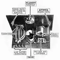
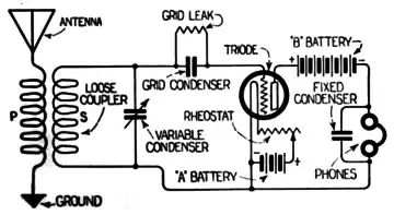
In the circuit, a capacitor (the grid condenser) couples a radio frequency signal (the carrier) to the control grid of an electron tube.[13] The capacitor also facilitates development of dc voltage on the grid. The impedance of the capacitor is small at the carrier frequency and high at the modulating frequencies.[14]
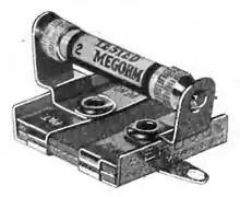
A resistor (the grid leak) is connected either in parallel with the capacitor or from the grid to the cathode. The resistor permits DC charge to "leak" from the capacitor[15] and is utilized in setting up the grid bias.[16]
At small carrier signal levels, typically not more than 0.1 volt,[17] the grid to cathode space exhibits non-linear resistance. Grid current occurs during 360 degrees of the carrier frequency cycle.[18] The grid current increases more during the positive excursions of the carrier voltage than it decreases during the negative excursions, due to the parabolic grid current versus grid voltage curve in this region.[19] This asymmetrical grid current develops a dc grid voltage that includes the modulation frequencies.[20][21][22] In this region of operation, the demodulated signal is developed in series with the dynamic grid resistance , which is typically in the range of 50,000 to 250,000 ohms.[23][24] and the grid condenser along with the grid capacitance form a low pass filter that determines the audio frequency bandwidth at the grid.[23][24]

At carrier signal levels large enough to make conduction from cathode to grid cease during the negative excursions of the carrier, the detection action is that of a linear diode detector.[25][26] Grid leak detection optimized for operation in this region is known as power grid detection or grid leak power detection.[27][28] Grid current occurs only on the positive peaks of the carrier frequency cycle. The coupling capacitor will acquire a dc charge due to the rectifying action of the cathode to grid path.[29] The capacitor discharges through the resistor (thus grid leak) during the time that the carrier voltage is decreasing.[30][31] The dc grid voltage will vary with the modulation envelope of an amplitude modulated signal.[32]
The plate current is passed through a load impedance chosen to produce the desired amplification in conjunction with the tube characteristics. In non-regenerative receivers, a capacitor of low impedance at the carrier frequency is connected from the plate to cathode to prevent amplification of the carrier frequency.[33]
Design
The capacitance of the grid condenser is chosen to be around ten times the grid input capacitance[34] and is typically 100 to 300 picofarads (pF), with the smaller value for screen grid and pentode tubes.[2][23]
The resistance and electrical connection of the grid leak along with the grid current determine the grid bias.[35] For operation of the detector at maximum sensitivity, the bias is placed near the point on the grid current versus grid voltage curve where maximum rectification effect occurs, which is the point of maximum rate of change of slope of the curve.[36][21][37] If a dc path is provided from the grid leak to an indirectly heated cathode or to the negative end of a directly heated cathode, negative initial velocity grid bias is produced relative to the cathode determined by the product of the grid leak resistance and the grid current.[38][39] For certain directly heated cathode tubes, the optimum grid bias is at a positive voltage relative to the negative end of the cathode. For these tubes, a dc path is provided from the grid leak to the positive side of the cathode or the positive side of the "A" battery; providing a positive fixed bias voltage at the grid determined by the dc grid current and the resistance of the grid leak.[40][21][41]
As the resistance of the grid leak is increased, the grid resistance increases and the audio frequency bandwidth at the grid decreases, for a given grid condenser capacitance.[23][24]
For triode tubes, the dc voltage at the plate is chosen for operation of the tube at the same plate current usually used in amplifier operation and is typically less than 100 volts.[42][43] For pentode and tetrode tubes, the screen grid voltage is chosen or made adjustable to permit the desired plate current and amplification with the chosen plate load impedance.[44]
For grid leak power detection, the time constant of the grid leak and condenser must be shorter than the period of the highest audio frequency to be reproduced.[45][46] A grid leak of around 250,000 to 500,000 ohms is suitable with a condenser of 100 pF.[28][45] The grid leak resistance for grid leak power detection can be determined by where is the highest audio frequency to be reproduced and is the grid condenser capacitance.[47] A tube requiring comparatively large grid voltage for plate current cutoff is of advantage (usually a low amplification factor triode).[27] The peak 100 percent modulated input signal voltage the grid leak detector can demodulate without excess distortion is about one half of the projected cutoff bias voltage ,[48] corresponding to a peak unmodulated carrier voltage of about one quarter of the projected cutoff bias.[49][27] For power grid detection using a directly heated cathode tube, the grid leak resistor is connected between the grid and the negative end of the filament, either directly or through the RF transformer.


Effect of tube type
Tetrode and pentode tubes provide significantly higher grid input impedance than triodes, resulting in less loading of the circuit providing the signal to the detector.[50] Tetrode and pentode tubes also produce significantly higher audio frequency output amplitude at small carrier input signal levels (around one volt or less) in grid leak detector applications than triodes.[51][52]
Advantages
- The grid leak detector potentially offers greater economy than use of separate diode and amplifier tubes.
- At small input signal levels, the circuit produces higher output amplitude than a simple diode detector.
Disadvantages
One potential disadvantage of the grid leak detector, primarily in non-regenerative circuits, is that of the load it can present to the preceding circuit.[33] The radio frequency input impedance of the grid leak detector is dominated by the tube's grid input impedance, which can be on the order of 6000 ohms or less for triodes, depending on tube characteristics and signal frequency. Other disadvantages are that it can produce more distortion and is less suitable for input signal voltages over a volt or two than the plate detector or diode detector.[53][54]
References
- Cruft Electronics Staff, Electronic Circuits and Tubes, New York: McGraw-Hill, 1947, p. 705
- H. A. Robinson, "The Operating Characteristics of Vacuum Tube Detectors", Part I, QST, vol. XIV, no. 8, p. 23, Aug. 1930
- J. Scott-Taggart, Thermionic Tubes in Radio Telegraphy and Telephony, London, UK: The Wireless Press LTD, 1921, p. 118
- S. Cabot, "Detection - Grid or Plate", QST, vol. XI, no. 3, p. 30, Mar. 1927
- E. H. Armstrong, "Some Recent Developments in the Audion Receiver", Proceedings of the Institute of Radio Engineers, vol. 3, no. 3, pp. 215-247, Sept. 1915
- Schematics of Zenith models 11, 12 and 14. Three battery-operated Zenith grid leak models of the 1920s.
- E. P. Wenaas, Radiola: the Golden Age of RCA, 1919 - 1929, Chandler, AZ: Sonoran Publishing LLC, 2007, p. 336
- Cruft Electronics Staff, P. 705
- K. R. Sturley, Radio Receiver Design (Part I), New York: John Wiley and Sons, 1947, p. 377
- Cruft Electronics Staff, P. 706
- The Radio Amateur's Handbook (55 ed.). The American Radio Relay League. 1978. p. 241.
- J. H. Reyner, "Grid Rectification. A Critical Examination of the Method", Experimental Wireless, vol. 1, no. 9, pp. 512-520, Jun. 1924
- W. L. Everitt, Communication Engineering, 2nd ed. New York: McGraw-Hill, 1937, p. 418
- J. Scott-Taggart, p. 119
- J. Scott-Taggart, p. 125
- A. A. Ghirardi, Radio Physics Course, 2nd ed. New York: Rinehart Books, 1932, p. 497
- F. E. Terman, Radio Engineering, 1st ed., New York: McGraw-Hill, 1932, pp. 292-293
- Signal Corps U.S. Army, The Principles Underlying Radio Communication, 2nd ed. Washington, DC: U.S.G.P.O., 1922, p. 478
- Landee, Davis, Albrecht, Electronic Designers' Handbook, New York: McGraw-Hill, 1957, pp. 7-103 - 7-108
- L.P. Smith, "Detector Action in High Vacuum Tubes", QST, vol. X, no. 12, pp. 14-17, Dec. 1926
- Cruft Electronics Staff, pp. 693 - 703
- F. E. Terman, "Some Principles of Grid-Leak Grid-Condenser Detection", Proceedings of the Institute of Radio Engineers, Vol. 16, No. 10, Oct. 1928, pp. 1384-1397
- W. L. Everitt, pp. 419-420
- Cruft Electronics Staff, p. 675
- Landee et al., p. 7-107
- E. E. Zepler, The Technique of Radio Design, New York: John Wiley and Sons, 1943, p. 104
- A. A. Ghirardi, p. 499
- W. L. Everitt, p. 421
- Signal Corps U.S. Army, p. 476
- Cruft Electronics Staff, p. 679
- Cruft Electronics Staff, p. 681
- K. R. Sturley, pp. 379-380
- F. E. Terman, 1932, p. 299
- J. Scott-Taggart, p. 125
- A. Hund, Phenomena in High Frequency Systems, New York: McGraw-Hill, 1936, p. 169
- J. H. Morecroft, Principles of Radio Communication, New York: John Wiley & Sons, Inc., 1921, p. 455
- Giacoletto, Lawrence Joseph (1977). Electronics Designers' Handbook. New York: McGraw-Hill. p. 9-27.
- Tomer, Robert B. (1960). Getting the Most Out of Vacuum Tubes. Indianapolis: Howard W. Sams & Co., Inc. / The Bobbs-Merrill Company, Inc. p. 28.
- RCA, The RCA Radiotron Manual, Technical Series R-10, Radio Corporation of America, p. 22
- Signal Corps U.S. Army, p. 477
- RCA, The RCA Radiotron Manual, Technical Series R-10, Radio Corporation of America, pp. 22-23, 25, 33
- RCA Radiotron Division, New All-Metal Radio Tubes, RCA Manufacturing Co., Inc., 1935, pp. 6-7
- H. A. Robinson, "The Operating Characteristics of Vacuum Tube Detectors", Part II, QST, vol. XIV, no. 9, p. 44, Sept. 1930
- E. E. Zepler, pp. 260-261
- J. H. Morecroft, p. 454
- K.R. Sturley, pp. 371-372
- K.R. Sturley, p. 23
- S. W. Amos, "The Mechanism of Leaky Grid Detection", Part II, Electronic Engineering, Sept. 1944, p. 158
- K. R. Sturley, p. 381
- H. A. Robinson, Part II, p. 45
- A. E. Rydberg, J. W. Doty, "The Superiority of Screen-Grid Detectors", QST, vol. XIV, no. 4, p. 43, Apr. 1930
- E. E. Zepler, p. 103
- H. A. Robinson, Part I, p. 25
Further reading
- Rutland, David (September 1994), Behind the Front Panel: The Design & Development of 1920's Radios, Wren, ISBN 978-1885391001
- Schematic of Philco model 84 A superheterodyne cathedral radio from 1933 that uses a regenerative detector. (Note: The capacitor for the detector's control grid is the "tickler coil" winding on the IF transformer.)
- "Radio Design Worksheet: No 39 — Detectors" (PDF). Radio. 29 (8): 51–52. August 1945.
