Group delay and phase delay
For a device such as an amplifier or telecommunications system, group delay and phase delay are device performance properties that help to characterize time delay, which is the amount of time for the various frequency components of a signal to pass through the device from input to output. If this timing does not sufficiently meet certain requirements, the device will contribute to signal distortion. For example, sufficient amounts of distortion equates to poor fidelity in video or audio, or to a high bit-error rate in a digital bit stream.
Phase delay, but not group delay, directly measures the device or system time delay of individual frequency components. For a modulated signal, which must be demodulated to recover the original signal intelligence, group delay must be used with the modulated signal to determine the time delay of the demodulated signal.
Discussed in this article is background theory on a device’s phase response property, from which the device’s phase delay and group delay properties can be calculated exactly. The article then goes on to illustrate the theory and use cases of these related device properties.
Introduction
Phase Delay
A linear time invariant (LTI) system or device has a phase response property from which the device’s phase delay property can be calculated exactly. Phase delay gives the time delay of the various frequency components of a signal. Since phase delay is a function of frequency giving time delay, a departure from the flatness of its function graph can reveal time delay differences among the various signal frequency components, in which case those differences will contribute to signal distortion, which is manifested as the output signal waveform shape being different from that of the input signal. The phase delay property in general does not give useful information if the device input is a modulated signal. For that, group delay must be used.
Group Delay
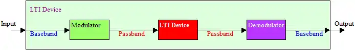
The basic use case for group delay is illustrated in Fig 1 which shows an outer LTI device that itself contains an inner (red block) LTI device. One version of the signal consists of frequency components in the original baseband frequency range, and another version of the signal carrying the same information is a modulated signal that consists of frequency components that have been shifted to a higher passband frequency range by a modulator. The demodulator does the opposite, shifting the frequency back down to the original baseband range. Ideally, the output (baseband) signal is a time delayed version of the input (baseband) signal where the waveform shape of the output is identical to that of the input.
In limited situations, the group delay property of the red inner device can be a proxy for the outer device phase delay; the outer device phase delay being the meaningful performance metric. For example, if the inner red device group delay is completely flat, the outer device will also have the ideal of a completely flat phase delay, where the contribution of distortion due to the outer LTI device’s phase response, determined entirely by the inner device’s possibly different phase response, is eliminated. In that case, both the group delay of the inner red device and the phase delay of the outer device give the same figure for the signal time delay from the baseband input to the baseband output. It is significant to note that it’s possible for the inner (red) device to have a very non-flat phase delay (but flat group delay), while the outer device has the ideal of a perfectly flat phase delay. This is fortunate because in LTI device design, a flat group delay is easier to achieve than a flat phase delay.
As is often the case for a radio system, the red LTI device in Fig 1 can represent two LTI devices in cascade, one at the sending end and the other at the receiving end.
Background
Frequency components of a signal
For a periodic signal, a frequency component is a sinusoid with properties that include time-based frequency and phase.
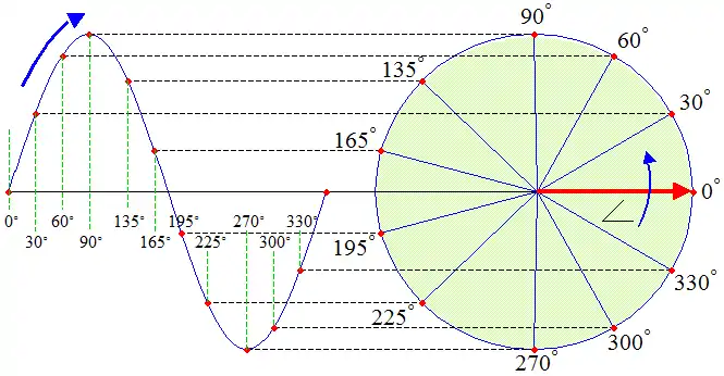
Generating a basic sinusoid
The sinusoid, with or without a time based frequency property, is generated by a circle as shown in the figure. In this example, the sinusoid is a sine wave that is traced out using the sin trig function.
.gif)
.gif)
When an increasing angle x makes a complete CCW rotation around the circle, one cycle of the function’s pattern is generated. Further increasing the angle beyond 360 degrees simply rotates around the circle again, completing another cycle, where each succeeding cycle repeats the same pattern, making the function periodic. (See slow animation.) The angle value has no limit, and so the number of times the pattern repeats itself also has no limit. Because of this, a sinusoid has no beginning and no end. A sinusoid function is based on either or both of the trig functions sin(x) and cos(x).
Theory
In linear time-invariant (LTI) system theory, control theory, and in digital or analog signal processing, the relationship between the input signal, and the output signal, , of an LTI system is governed by a convolution operation:


Or, in the frequency domain,

where


and
- .

Here is the time-domain impulse response of the LTI system and , , , are the Laplace transforms of the input , output , and impulse response , respectively. is called the transfer function of the LTI system and, like the impulse response , fully defines the input-output characteristics of the LTI system.


Suppose that such a system is driven by a quasi-sinusoidal signal, that is a sinusoid having an amplitude envelope that is slowly changing relative to the frequency of the sinusoid. Mathematically, this means that the quasi-sinusoidal driving signal has the form


and the slowly changing amplitude envelope means that


Then the output of such an LTI system is very well approximated as

Here and , the group delay and phase delay respectively, are given by the expressions below (and potentially are functions of the angular frequency ). The sinusoid, as indicated by the zero crossings, is delayed in time by phase delay, . The envelope of the sinusoid is delayed in time by the group delay, .


In a linear phase system (with non-inverting gain), both and are constant (i.e. independent of ) and equal, and their common value equals the overall delay of the system; and the unwrapped phase shift of the system (namely ) is negative, with magnitude increasing linearly with frequency .

More generally, it can be shown that for an LTI system with transfer function driven by a complex sinusoid of unit amplitude,

the output is

where the phase shift is


Additionally, it can be shown that the group delay, , and phase delay, , are frequency-dependent, and they can be computed from the properly unwrapped phase shift by

- .

Group delay in optics
In physics, and in particular in optics, the term group delay has the following meanings:
- 1. The rate of change of the total phase shift with respect to angular frequency,
- through a device or transmission medium, where is the total phase shift in radians, and is the angular frequency in radians per unit time, equal to , where is the frequency (hertz if group delay is measured in seconds).


- 2. In an optical fiber, the transit time required for optical power, traveling at a given mode's group velocity, to travel a given distance.
- Note: For optical fiber dispersion measurement purposes, the quantity of interest is group delay per unit length, which is the reciprocal of the group velocity of a particular mode. The measured group delay of a signal through an optical fiber exhibits a wavelength dependence due to the various dispersion mechanisms present in the fiber.
It is often desirable for the group delay to be constant across all frequencies; otherwise there is temporal smearing of the signal. Because group delay is , as defined in (1), it therefore follows that a constant group delay can be achieved if the transfer function of the device or medium has a linear phase response (i.e., where the group delay is a constant). The degree of nonlinearity of the phase indicates the deviation of the group delay from a constant.


Group delay in audio
Group delay has some importance in the audio field and especially in the sound reproduction field. Many components of an audio reproduction chain, notably loudspeakers and multiway loudspeaker crossover networks, introduce group delay in the audio signal. It is therefore important to know the threshold of audibility of group delay with respect to frequency, especially if the audio chain is supposed to provide high fidelity reproduction. The best thresholds of audibility table has been provided by Blauert & Laws (1978).
| Frequency | Threshold | Periods (Cycles) |
|---|---|---|
| 500 Hz | 3.2 ms | 1.6 |
| 1 kHz | 2 ms | 2 |
| 2 kHz | 1 ms | 2 |
| 4 kHz | 1.5 ms | 6 |
| 8 kHz | 2 ms | 16 |
Flanagan, Moore and Stone conclude that at 1, 2 and 4 kHz, a group delay of about 1.6 ms is audible with headphones in a non-reverberant condition.[1]
True time delay
A transmitting apparatus is said to have true time delay (TTD) if the time delay is independent of the frequency of the electrical signal.[2][3] TTD is an important characteristic of lossless and low-loss, dispersion free, transmission lines. TTD allows for a wide instantaneous signal bandwidth with virtually no signal distortion such as pulse broadening during pulsed operation.
See also
- Audio system measurements
- Bessel filter
- Eye pattern
- Group velocity — "The group velocity of light in a medium is the inverse of the group delay per unit length."[4]
- Spectral phase — "The group delay can be defined as the derivative of the spectral phase with respect to angular frequency."[5]
References
![]() This article incorporates public domain material from the General Services Administration document: "Federal Standard 1037C".
This article incorporates public domain material from the General Services Administration document: "Federal Standard 1037C".
- Flanagan, Sheila; Moore, Brian C. J.; Stone, Michael A. (2005), "Discrimination of Group Delay in Clicklike Signals Presented via Headphones and Loudspeakers", Journal of the Audio Engineering Society, 53 (7/8): 593–611
- "True Time Delay". Microwaves101, IEEE.
- Julius O. Smith III. "Phase Delay and Group Delay". Department of Electrical Engineering, Stanford University.
- https://www.rp-photonics.com/group_delay.html
- https://www.rp-photonics.com/spectral_phase.html
- Blauert, J.; Laws, P. (May 1978), "Group Delay Distortions in Electroacoustical Systems", Journal of the Acoustical Society of America, 63 (5): 1478–1483, Bibcode:1978ASAJ...63.1478B, doi:10.1121/1.381841
External links
- Discussion of Group Delay in Loudspeakers
- Group Delay Explanations and Applications
- Blauert, J.; Laws, P. (May 1978), "Group Delay Distortions in Electroacoustical Systems", Journal of the Acoustical Society of America 63 (5): 1478–1483
- "Introduction to Digital Filters with Audio Applications", Julius O. Smith III, (September 2007 Edition).
