Hall-effect sensor
A Hall-effect sensor (or simply Hall sensor) is a device to measure the magnitude of a magnetic field. Its output voltage is directly proportional to the magnetic field strength through it.

Hall-effect sensors are used for proximity sensing, positioning, speed detection, and current sensing applications.[1]
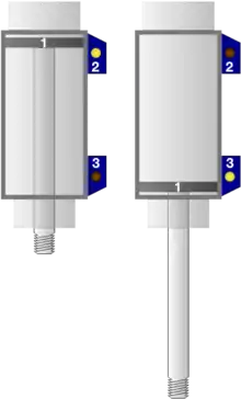
Frequently, a Hall sensor is combined with threshold detection, so that it acts as and is called a switch. Commonly seen in industrial applications such as the pictured pneumatic cylinder, they are also used in consumer equipment; for example, some computer printers use them to detect missing paper and open covers. They can also be used in computer keyboards, an application that requires ultra-high reliability. Another use of a Hall sensor is in the creation of MIDI organ pedal-boards, where the movement of a "key" on the pedal-board is translated as an on/off switch by Hall sensors.
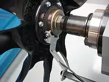
Hall sensors are commonly used to time the speed of wheels and shafts, such as for internal combustion engine ignition timing, tachometers and anti-lock braking systems. They are used in brushless DC electric motors to detect the position of the permanent magnet. In the pictured wheel with two equally spaced magnets, the voltage from the sensor peaks twice for each revolution. This arrangement is commonly used to regulate the speed of disk drives.
Hall probe
A Hall probe contains an indium-compound semiconductor crystal such as indium antimonide, mounted on an aluminum backing plate and encapsulated in the probe head. The plane of the crystal is perpendicular to the probe handle. Connecting leads from the crystal are brought down through the handle to the circuit box.
When the Hall probe is held so that the magnetic field lines are passing at right angles through the sensor of the probe, the meter gives a reading of the value of magnetic flux density (B). A current is passed through the crystal, which, when placed in a magnetic field, has a "Hall effect" voltage developed across it. The Hall effect is seen when a conductor is passed through a uniform magnetic field. The natural electron drift of the charge carriers causes the magnetic field to apply a Lorentz force (the force exerted on a charged particle in an electromagnetic field) to these charge carriers, resulting in charge separation, with a buildup of either positive or negative charges on the bottom or on the top of the plate. The crystal measures 5 mm square. The probe handle, being made of a non-ferrous material, has no disturbing effect on the field.
A Hall probe should be calibrated against a known value of magnetic field strength. For a solenoid the Hall probe is placed in the centre.
Working principle
In a Hall-effect sensor, a thin strip of metal has a current applied along it. In the presence of a magnetic field, the electrons in the metal strip are deflected toward one edge, producing a voltage gradient across the short side of the strip (perpendicular to the feed current). Hall-effect sensors have an advantage over inductive sensors in that, while inductive sensors respond to a changing magnetic field that induces current in a coil of wire and produces voltage at its output, Hall-effect sensors can detect static (non-changing) magnetic fields.
In its simplest form, the sensor operates as an analog transducer, directly returning a voltage. With a known magnetic field, its distance from the Hall plate can be determined. Using groups of sensors, the relative position of the magnet can be deduced.
When a beam of charged particles passes through a magnetic field, forces act on the particles, and the beam is deflected from a straight path. The flow of electrons through a conductor forms a beam of charged carriers. When a conductor is placed in a magnetic field perpendicular to the direction of the electrons, they are deflected from a straight path. As a consequence, one plane of the conductor becomes negatively charged, and the opposite side becomes positively charged. The voltage between these planes is called the Hall voltage.[2]
When the force on the charged particles from the electric field balances the force produced by the magnetic field, the separation of charges stops. If the current is not changing, then the Hall voltage is a measure of the magnetic flux density. Basically, there are two kinds of Hall-effect sensors: linear, which means that the output of voltage linearly depends on magnetic flux density; and threshold, which means that there is a sharp decrease of output voltage at some magnetic flux density. This experiment was the one to demonstrate that there are only negative charges free to move in a conductor. Before this, it was believed that positive charges move in a current-carrying conductor. This experiment is known as the Hall experiment.
Materials
The key factor determining sensitivity of Hall-effect sensors is high electron mobility. As a result, the following materials are especially suitable for Hall-effect sensors:
- gallium arsenide (GaAs),
- indium arsenide (InAs),
- indium phosphide (InP),
- indium antimonide (InSb),
- graphene.[3]
Signal processing and interface
Hall-effect sensors are linear transducers. As a result, such sensors require a linear circuit for processing of the sensor output signal. Such a linear circuit:
- provides a constant driving current to the sensors,
- amplifies the output signal.
In some cases, the linear circuit may cancel the offset voltage of Hall-effect sensors. Moreover, AC modulation of the driving current may also reduce the influence of this offset voltage.
Hall-effect sensors with linear transducers are commonly integrated with digital electronics.[4] This enables advanced corrections to the sensor characteristics (e.g. temperature-coefficient corrections) and digital interfacing to microprocessor systems. In some solutions of IC Hall-effect sensors a DSP is used, which provides more choices among processing techniques.[1]:167
The Hall-effect sensor interfaces may include input diagnostics, fault protection for transient conditions, and short/open-circuit detection. It may also provide and monitor the current to the Hall-effect sensor itself. There are precision IC products available to handle these features.
Advantages
A Hall-effect sensor may operate as an electronic switch.
- Such a switch costs less than a mechanical switch and is much more reliable.
- It can be operated at higher frequencies than a mechanical switch.
- It does not suffer from contact bounce because a solid-state switch with hysteresis is used rather than a mechanical contact.
- It is not affected by environmental contaminants, since the sensor is in a sealed package. Therefore, it can be used under severe conditions.
In the case of linear sensor (for the magnetic-field-strength measurements), a Hall-effect sensor:
- can measure a wide range of magnetic fields,
- can measure both sign and amplitude,
- can be flat.
Disadvantages
Hall-effect sensors provide much lower measuring accuracy than fluxgate magnetometers or magnetoresistance-based sensors. Moreover, Hall-effect sensors drift significantly, requiring compensation.
Applications
Position sensing
Sensing the presence of magnetic objects (connected with the position sensing) is the most common industrial application of Hall-effect sensors, especially those operating in the switch mode (on/off mode). The Hall-effect sensors are also used in brushless DC motors to sense the position of the rotor and to switch the transistors in the right sequence.
Smartphones use Hall sensors to determine whether the flip cover accessory is closed.[5] See Galaxy S4 accessories.
Direct-current (DC) transformers
Hall-effect sensors may be utilized for contactless measurements of direct current in current transformers. In such a case the Hall-effect sensor is mounted in the gap in magnetic core around the current conductor.[6] As a result, the DC magnetic flux can be measured, and the DC current in the conductor can be calculated.
Automotive fuel-level indicator
The Hall sensor is used in some automotive fuel-level indicators. The main principle of operation of such indicator is position sensing of a floating element.[7] This can either be done by using a vertical float magnet or a rotating-lever sensor.
- In a vertical float system a permanent magnet is mounted on the surface of a floating object. The current-carrying conductor is fixed on the top of the tank, lining up with the magnet. When the level of fuel rises, an increasing magnetic field is applied on the current, resulting in higher Hall voltage. As the fuel level decreases, the Hall voltage also decreases. The fuel level is indicated and displayed by proper signal condition of Hall voltage.
- In a rotating-lever sensor a diametrically magnetized ring magnet rotates about a linear Hall sensor. The sensor only measures the perpendicular (vertical) component of the field. The strength of the field measured correlates directly to the angle of the lever and thus the level of the fuel tank.
Keyboard switch
Hall-effect switches for computer keyboards were developed in the late 1960s by Everett A. Vorthmann and Joseph T. Maupin at Honeywell.[8] Due to high manufacturing costs these keyboards were often reserved for high-reliability applications such as aerospace and military. As mass-production costs have reduced, increasing number of consumer models have become available. Mechanical keyboards from Acepad Technology[9] use Hall-effect switches; the Input Club Keystone[10] and Wooting Lekker Switch[11] are in progress.
See also
References
- Ramsden, Edward (2006). Hall-effect sensors: theory and applications (2, illustrated ed.). Elsevier. ISBN 978-0-7506-7934-3.
- Popović, R. S. (2004). Hall effect devices (2, illustrated ed.). CRC Press. ISBN 978-0-7503-0855-7.
- Petruk, Oleg; Szewczyk, Roman; Ciuk, Tymoteusz; et al. (2014). Sensitivity and Offset Voltage Testing in the Hall-Effect Sensors Made of Graphene. Advances in Intelligent Systems and Computing. 267. Springer. p. 631. doi:10.1007/978-3-319-05353-0_60. ISBN 978-3-319-05352-3.
- "Hall Effect Sensor Voltage Regulation and Power Management". phareselectronics.com. Retrieved 26 May 2015.
- "ZenFone 5 (A500CG)". asus.com. Retrieved 2 September 2017.
- Petruk, O.; Szewczyk, R.; Salach, J.; Nowicki, M. (2014). Digitally Controlled Current Transformer with Hall Sensor. Advances in Intelligent Systems and Computing. 267. Springer. p. 641. doi:10.1007/978-3-319-05353-0_61. ISBN 978-3-319-05352-3.
- "Liquid Level Sensing: Measuring Liquid Levels Using Hall Effect Sensors" (PDF). infineon.com. 12 February 2009. Retrieved 2 September 2017.
- Vorthmann, Everett A.; Maupin, Joseph T. (May 1969). "Solid state keyboard". AFIPS Spring Joint Computing Conference 1969: 149–159. doi:10.1145/1476793.1476823. S2CID 7540281.
- Limmen, Calder (May 10, 2019). "What are Hall Effect keyboard Switches". Wooting Developer Blog. Retrieved July 11, 2019.
- "Keystone — The Future of Mechanical Keyboards". Kickstarter. Retrieved 2020-08-20.
- "Wooting's Lekker switch". wooting.io. Retrieved 2020-08-20.
Further reading
- Baumgartner, A.; Ihn, T.; Ensslin, K.; Papp, G.; Peeters, F.; Maranowski, K.; Gossard, A. C. (2006). "Classical Hall effect in scanning gate experiments". Phys. Rev. B. 74 (16): 165426. Bibcode:2006PhRvB..74p5426B. doi:10.1103/PhysRevB.74.165426. hdl:10067/613600151162165141. S2CID 121163404.
External links
 Media related to Hall sensors at Wikimedia Commons