Planar (computer graphics)
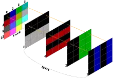
In computer graphics, planar is the method of arranging pixel data into several bitplanes of RAM. Each bit in a bitplane is related to one pixel on the screen. Unlike packed, high color, or true color graphics, the whole dataset for an individual pixel isn't in one specific location in RAM, but spread across the bitplanes that make up the display. Planar arrangement determines how pixel data is laid out it memory, not how the data for a pixel is interpreted; pixel data in a planar arrangement could encode either indexed or direct color.
This scheme originated in the early days of computer graphics. The memory chips of this era can not supply data fast enough on their own to generate a picture on a TV screen or monitor from a large framebuffer.[1] By splitting the data up into multiple planes, each plane can be stored on a separate memory chip. These chips can then be read in parallel at a slower rate, allowing graphical display on modest hardware. The EGA video adapter on early IBM PC computers uses planar arrangement in color graphical modes for this reason. The later VGA includes one non-planar mode which sacrifices memory efficiency for more convenient access.[2]
Examples
On a chunky display with 4-bits-per-pixel and a RGBI palette, each byte represents two pixels, with 16 different colors available for each pixel. Four consecutive pixels are stored in two consecutive bytes as follows:
| Byte index | 0 | 1 | ||
|---|---|---|---|---|
| Byte value (decimal) | 1 | 35 | ||
| Byte value (hexadecimal) | 0x01 | 0x23 | ||
| Nybble value (binary) | 0000 | 0001 | 0010 | 0011 |
| Nybble value (decimal) | 0 | 1 | 2 | 3 |
| Resulting pixel | Black | Blue | Green | Cyan |
Whereas a planar scheme could use 2 bitplanes, providing for a 4 color display. Eight pixels would be stored as 2 bytes non-contiguously in memory:
| Byte index | 0 | Byte value | ||||||||
|---|---|---|---|---|---|---|---|---|---|---|
| Bit index | 0 | 1 | 2 | 3 | 4 | 5 | 6 | 7 | hexadecimal | decimal |
| Plane 0 | 0 | 1 | 0 | 1 | 0 | 0 | 0 | 0 | 0x50 | 80 |
| Plane 1 | 0 | 0 | 1 | 1 | 0 | 0 | 0 | 0 | 0x30 | 48 |
| Resulting pixel | 0 | 1 | 2 | 3 | 0 | 0 | 0 | 0 | ||
In the planar example, 2 bytes represent 8 pixels with 4 available colors, where the packed pixel example uses 2 bytes to represent fewer pixels but with more colors. Adding planes will increase the number of colors available at the cost of requiring more memory. For example, using 4 planes makes 24=16 colors available, but it would then take 4 bytes to represent 8 pixels (making it equivalent in terms of memory usage and available colors to the packed arrangement example).
Advantages and Disadvantages
Planar arrangements offer space and time efficiencies over packed arrangements at bit depths that aren't powers of 2. As an example, consider 3 bpp, allowing 8 colors. With planar arrangements, this simply requires 3 planes. With packed arrangements, supporting exactly 3 bpp would require either allowing pixels to cross byte boundaries (incurring time costs due to complications with addressing and unpacking pixels) or padding (incurring space costs, as each byte would store 2 pixels and have 2 unused bits); historically, this is one reason (though not necessarily the main one) packed pixels used bit depths that fit evenly into bytes.
Planar arrangements allow for faster bit depth switching: planes are added or discarded and (if colors are indexed) the palette is extended or truncated. Consequently, support for higher bit depths can be added with little to no impact on older software. Ease of bit depth switching also allow elements with different bit depths to be easily used together.
A disadvantage of planar arrangements is that more RAM address cycles are needed for scrolling and animations.
See also
References
- Rogers, David F. (1985). Procedural Elements for Computer Graphics. McGraw-Hill. p. 13. ISBN 0-07-053534-5.
- "VGA Hardware - OSDev Wiki". wiki.osdev.org. Retrieved September 4, 2017.
