Potentiometer (measuring instrument)
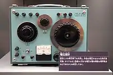
A potentiometer is an instrument for measuring voltage or 'potential difference' by comparison of an unknown voltage with a known reference voltage. If a sensitive indicating instrument is used, very little current is drawn from the source of the unknown voltage. Since the reference voltage can be produced from an accurately calibrated voltage divider, a potentiometer can provide high precision in measurement. The method was described by Johann Christian Poggendorff around 1841 and became a standard laboratory measuring technique.[1]
In this arrangement, a fraction of a known voltage from a resistive slide wire is compared with an unknown voltage by means of a galvanometer. The sliding contact or wiper of the potentiometer is adjusted and the galvanometer briefly connected between the sliding contact and the unknown voltage. The deflection of the galvanometer is observed and the sliding tap adjusted until the galvanometer no longer deflects from zero. At that point the galvanometer draws no current from the unknown source, and the magnitude of voltage can be calculated from the position of the sliding contact.
This null balance measuring method is still important in electrical metrology and standards work and is also used in other areas of electronics.
Measurement potentiometers are divided into four main classes listed below.
Principle of operation

The principle of a potentiometer is that the potential dropped across a segment of a wire of uniform cross-section carrying a constant current is directly proportional to its length. The potentiometer is a simple device used to measure the electrical potentials (or compare the e.m.f of a cell). One form of potentiometer is a uniform high-resistance wire attached to an insulating support, marked with a linear measuring scale. In use, an adjustable regulated voltage source E, of greater magnitude than the potential to be measured, is connected across the wire so as to pass a steady current through it.
Between the end of the wire and any point along it will be a potential proportional to the length of wire to that point. By comparing the potential at points along the wire with an unknown potential, the magnitude of the unknown potential can be determined. The instrument used for comparison must be sensitive, but need not be particularly well-calibrated or accurate so long as its deflection from zero position can be easily detected.
Constant current potentiometer

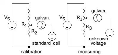
R1 is the resistance of the entire resistance wire. The arrow head represents the moving wiper.
In this circuit, the ends of a uniform resistance wire R1 are connected to a regulated DC supply VS for use as a voltage divider. The potentiometer is first calibrated by positioning the wiper (arrow) at the spot on the R1 wire that corresponds to the voltage of a standard cell so that
A standard electrochemical cell is used whose emf is known (e.g. 1.0183 volts for a Weston standard cell).[2][3]
The supply voltage VS is then adjusted until the galvanometer shows zero, indicating the voltage on R2 is equal to the standard cell voltage.
An unknown DC voltage, in series with the galvanometer, is then connected to the sliding wiper, across a variable-length section R3 of the resistance wire. The wiper is moved until no current flows into or out of the source of unknown voltage, as indicated by the galvanometer in series with the unknown voltage. The voltage across the selected R3 section of wire is then equal to the unknown voltage. The final step is to calculate the unknown voltage from the fraction of the length of the resistance wire that was connected to the unknown voltage.
The galvanometer does not need to be calibrated, as its only function is to read zero or not zero. When measuring an unknown voltage and the galvanometer reads zero, no current is drawn from the unknown voltage and so the reading is independent of the source's internal resistance, as if by a voltmeter of infinite resistance.
Because the resistance wire can be made very uniform in cross-section and resistivity, and the position of the wiper can be measured easily, this method can be used to measure unknown DC voltages greater than or less than a calibration voltage produced by a standard cell without drawing any current from the standard cell.
If the potentiometer is attached to a constant voltage DC supply such as a lead–acid battery, then a second variable resistor (not shown) can be used to calibrate the potentiometer by varying the current through the R1 resistance wire.
If the length of the R1 resistance wire is AB, where A is the (-) end and B is the (+) end, and the movable wiper is at point X at a distance AX on the R3 portion of the resistance wire when the galvanometer gives a zero reading for an unknown voltage, the distance AX is measured or read from a pre-printed scale next to the resistance wire. The unknown voltage can then be calculated:
Constant resistance potentiometer
The constant resistance potentiometer is a variation of the basic idea in which a variable current is fed through a fixed resistor. These are used primarily for measurements in the millivolt and microvolt range.
Microvolt potentiometer
This is a form of the constant resistance potentiometer described above but designed to minimize the effects of contact resistance and thermal emf. This equipment is satisfactorily used down to readings of 1000 nV or so.
Thermocouple potentiometer
Another development of the standard types was the 'thermocouple potentiometer' especially adapted for temperature measurement with thermocouples. [4] Potentiometers for use with thermocouples also measure the temperature at which the thermocouple wires are connected, so that cold-junction compensation may be applied to correct the apparent measured EMF to the standard cold-junction temperature of 0 degrees C.
Analytical chemistry
To make a potentiometric determination of an analyte in a solution, the potential of the cell is measured. This measurement must be corrected for the reference and junction potentials. It can also be used in standardisation methods. The concentration of the analyte can then be calculated from the Nernst Equation. Many varieties of this basic principle exist for quantitative measurements.
Metre bridge
A metre bridge is a simple type of potentiometer which may be used in school science laboratories to demonstrate the principle of resistance measurement by potentiometric means. A resistance wire is laid along the length of a metre rule and contact with the wire is made through a galvanometer by a slider. When the galvanometer reads zero, the ratio between the lengths of wire to the left and right of the slider is equal to the ratio between the values of a known and an unknown resistor in a parallel circuit.[5]
References
- Thomas B. Greenslade, Jr. "The Potentiometer". Physics.kenyon.edu. Retrieved 2013-06-01.
- Kenyon.edu Dept of Physics.
- scenta.co.uk Archived 2012-09-11 at Archive.today Scenta.
- Kenyon.edu Dept of Physics. Thermodynamics: Thermocouple Potentiometer.
- "Ian Hickson's Metre Bridge Experiment". Academia.hixie.ch. Retrieved 2013-06-01.
External links
| Wikimedia Commons has media related to Potentiometers (measuring instruments). |