Punch press
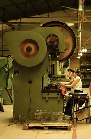
A punch press is a type of machine press used to cut holes in material. It can be small and manually operated and hold one simple die set, or be very large, CNC operated, with a multi-station turret and hold a much larger and complex die set.
Description
Punch presses are large machines with either a 'C' type frame, or a 'portal' (bridge) type frame. The C type has the hydraulic ram at the top foremost part, whereas the portal frame is much akin to a complete circle with the ram being centered within the frame to stop frame deflection or distortion.
C type presses have a bed plate which is used to lock the die bottom bolster. For locking the die, T-bolts are used and so this plate contains T-slots into which T-bolts are slid in. These slots are placed diagonally and with a slot horizontal to the longer side of the plate, is the general practice. These slots run up to a central hole made in the plate, the hole being large enough to accommodate another bush with a hole, the hole being used for dropping the punched part to the bottom of the press. The top of the tool butted against a vertical sliding ram with a clamping system which accommodates only a particular diameter of a threaded cylindrical member called the "shank" of the tool. The bottom portion of the tool is locked to the bottom bed plate and the top portion of the tool is locked to the sliding ram. Top and bottom portions of the tool are generally guided by suitable pillar and bush assemblies, which gives safety to the punching elements of the tool.
Generally the tool is placed slightly above the bottom bed plate by providing two parallel blocks accurately ground to the same size. This is a necessary action since many tools, scrap (cut pieces which are a waste) is discharged through the bottom element of the tool, not necessarily in the centre of the tool. The scrap or the blank (the required portion) come out from the die at different places. These have to be taken out horizontally from between the parallels placed. Otherwise they get accumulated inside the tool itself and cause severe damage to the tool.
In very heavy presses with higher tonnage, the sliding ram has also a thick plate with T slots for locking the top plate of the tool (called the top bolster). In such cases the threaded cylinder called shank is not attached to the tool. The clamps are either mechanical (manually operated using spanners) or air operated varieties.
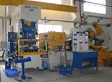
Turret type punch press machines have a table or bed with brushes or rollers to allow the sheet metal workpiece to traverse with low friction. Brushes are used where scratches on the workpiece must be minimized, as with brushed aluminium or high polished materials.
The punch press is characterized by parameters such as:
- Frame type
- Mechanism of delivering power to the ram (mechanical, electro-mechanical or hydraulic)
- Size of working area (e.g., 2500 x 1250 mm)
- Single or multiple station
- Force rating (for example, 20 tons)
- The type of tool shop and its capacity (e.g., store revolving type, capacity 34 tool)
- Speed or productivity (typically characterized by the speed of strokes with a step movement of 25 and 1 mm)
- Speed of movement without shock (speed-load displacement)
- Maximum weight of workpiece
- Safety features
- Power consumption
- The type of software
Punch presses are usually referred to by their tonnage and table size. In a production environment a 30-ton press is mostly the machine used today. The tonnage needed to cut and form the material is well known, so sizing tooling for a specific job is a fairly straightforward task. According to the requirement the tonnage may even go up to 2000 to 2500 ton presses.
Die set
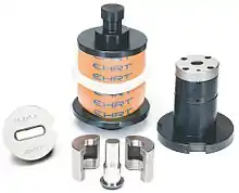
A die set consists of a set of punches (male) and dies (female) which, when pressed together, form a hole in a workpiece (and may also deform the workpiece in some desired manner). The punches and dies are removable, with the punch being attached to the ram during the punching process. The ram moves up and down in a vertically linear motion, forcing the punch through the material into the die.
Axis
The main bed of most machines is called the 'X' axis, with the 'Y' axis being at right angles to that and allowed to traverse under CNC control. Dependent on the size of the machine, the beds, and the sheet metal workpiece weight, the motors required to move these axis tables will vary in size and power. Older styles of machines used DC motors; however, with advances in technology, today's machines mostly use AC brushless motors for drives.
CNC-controlled operation
To start a cycle, the CNC controller commands the drives to move the table along the X and the Y axis to a desired position. Once in position, the control initiates the punching sequence and pushes the ram from top dead center (TDC) to bottom dead center (BDC) through the material plane. (The terms BDC and TDC go back to older presses with pneumatic or hydraulic clutches. On today's machines BDC/TDC do not actually exist but are still used for the bottom and top of a stroke.)
On its stroke from TDC to BDC, the punch enters the material, pushing it through the die, obtaining the shape determined by the design of the punch and die set. The piece of material (slug) cut from the workpiece is ejected through the die and bolster plate and collected in a scrap container.[1] The return to TDC signals to the control to begin the next cycle.
The punch press is used for high volume production. Cycle times are often measured in milliseconds. Material yield is measured as a percentage of parts to waste per sheet processed. CAD/CAM programs maximize yield by nesting parts in the layout of the sheet.
Drive type
Flywheel drive
Most punch presses today are hydraulically powered. Older machines, however, have mechanically driven rams, meaning the power to the ram is provided by a heavy, constantly rotating flywheel. The flywheel drives the ram using a Pitman arm. In the 19th century, the flywheels were powered by leather drive belts attached to line shafting, which in turn ran to a steam plant. In the modern workplace, the flywheel is powered by an electric motor.
Mechanical punch press
Mechanical punch presses fall into two distinct types, depending on the type of clutch or braking system with which they are equipped. Generally, older presses are "full revolution" presses that require a full revolution of the crankshaft for them to come to a stop. Full revolution clutch presses are known to be dangerous and outlawed in many countries unless the pinch point is fully guarded. This is because the braking mechanism depends on a set of raised keys or "dogs" to fall into matching slots to stop the ram. A full revolution clutch can only bring the ram to a stop at the same location - top dead center. Newer presses are often "part revolution" presses equipped with braking systems identical to the brakes on commercial trucks. When air is applied, a band-type brake expands and allows the crankshaft to revolve. When the stopping mechanism is applied the air is bled, causing the clutch to open and the braking system to close, stopping the ram in any part of its rotation. Modern part revolution clutch and brake units are normally combined units that operate in a fail safe mode, a dual air safety valve engages clutch and starts slide motion and brake is applied by springs.
Hydraulic punch press
Hydraulic punch presses power the ram with a hydraulic cylinder rather than a flywheel, and are either valve controlled or valve and feedback controlled. Valve controlled machines usually allow a one stroke operation allowing the ram to stroke up and down when commanded. Controlled feedback systems allow the ram to be proportionally controlled to within fixed points as commanded. This allows greater control over the stroke of the ram, and increases punching rates as the ram no longer has to complete the traditional full stroke up and down but can operate within a very short window of stroke.
Servo drive turret punch press
A servo drive turret punch press uses twin AC servo drives directly coupled to the drive shaft. This drive system combines the simplicity of the original clutch and brake technology with the speed of a hydraulic ram driven system. This results in high performance, reliability, and lower operating costs. A servo drive press system has no complex hydraulics or oil-cooling chillers, thus reducing maintenance and repair costs. A turret press can be equipped with advanced technology that stores and reuses energy generated during ram deceleration, providing extended electrical power savings.
See also
References
- Todd, Allen & Alting 1994, pp. 107–108.
Bibliography
- Todd, Robert H.; Allen, Dell K.; Alting, Leo (1994), Manufacturing Processes Reference Guide, Industrial Press Inc., ISBN 0-8311-3049-0.