Forging
Forging is a manufacturing process involving the shaping of metal using localized compressive forces. The blows are delivered with a hammer (often a power hammer) or a die. Forging is often classified according to the temperature at which it is performed: cold forging (a type of cold working), warm forging, or hot forging (a type of hot working). For the latter two, the metal is heated, usually in a forge. Forged parts can range in weight from less than a kilogram to hundreds of metric tons.[1][2] Forging has been done by smiths for millennia; the traditional products were kitchenware, hardware, hand tools, edged weapons, cymbals, and jewellery. Since the Industrial Revolution, forged parts are widely used in mechanisms and machines wherever a component requires high strength; such forgings usually require further processing (such as machining) to achieve a finished part. Today, forging is a major worldwide industry.[3]
History
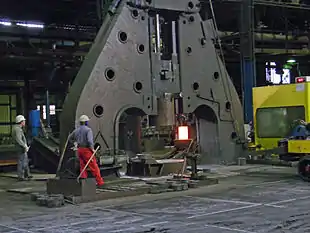
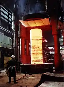
Forging is one of the oldest known metalworking processes.[1] Traditionally, forging was performed by a smith using hammer and anvil, though introducing water power to the production and working of iron in the 12th century allowed the use of large trip hammers or power hammers that increased the amount and size of iron that could be produced and forged. The smithy or forge has evolved over centuries to become a facility with engineered processes, production equipment, tooling, raw materials and products to meet the demands of modern industry.
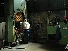
In modern times, industrial forging is done either with presses or with hammers powered by compressed air, electricity, hydraulics or steam. These hammers may have reciprocating weights in the thousands of pounds. Smaller power hammers, 500 lb (230 kg) or less reciprocating weight, and hydraulic presses are common in art smithies as well. Some steam hammers remain in use, but they became obsolete with the availability of the other, more convenient, power sources.
Advantages and disadvantages
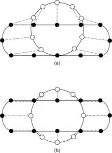
Forging can produce a piece that is stronger than an equivalent cast or machined part. As the metal is shaped during the forging process, its internal grain texture deforms to follow the general shape of the part. As a result, the texture variation is continuous throughout the part, giving rise to a piece with improved strength characteristics.[4] Additionally, forgings can achieve a lower total cost than casting or fabrication. Considering all the costs that are incurred in a product's life cycle from procurement to lead time to rework, and factoring in the costs of scrap, and downtime and other quality considerations, the long-term benefits of forgings can outweigh the short-term cost savings that castings or fabrications might offer.[5]
Some metals may be forged cold, but iron and steel are almost always hot forged. Hot forging prevents the work hardening that would result from cold forming, which would increase the difficulty of performing secondary machining operations on the piece. Also, while work hardening may be desirable in some circumstances, other methods of hardening the piece, such as heat treating, are generally more economical and more controllable. Alloys that are amenable to precipitation hardening, such as most aluminium alloys and titanium, can be hot forged, followed by hardening.
Production forging involves significant capital expenditure for machinery, tooling, facilities and personnel. In the case of hot forging, a high-temperature furnace (sometimes referred to as the forge) is required to heat ingots or billets. Owing to the size of the massive forging hammers and presses and the parts they can produce, as well as the dangers inherent in working with hot metal, a special building is frequently required to house the operation. In the case of drop forging operations, provisions must be made to absorb the shock and vibration generated by the hammer. Most forging operations use metal-forming dies, which must be precisely machined and carefully heat-treated to correctly shape the workpiece, as well as to withstand the tremendous forces involved.
Processes
There are many different kinds of forging processes available; however, they can be grouped into three main classes:[1]
- Drawn out: length increases, cross-section decreases
- Upset: length decreases, cross-section increases
- Squeezed in closed compression dies: produces multidirectional flow
Common forging processes include: roll forging, swaging, cogging, open-die forging, impression-die forging(close die forging), press forging, cold forging automatic hot forging and upsetting.[1][6]
Temperature
All of the following forging processes can be performed at various temperatures; however, they are generally classified by whether the metal temperature is above or below the recrystallization temperature. If the temperature is above the material's recrystallization temperature it is deemed hot forging; if the temperature is below the material's recrystallization temperature but above 30% of the recrystallization temperature (on an absolute scale) it is deemed warm forging; if below 30% of the recrystallization temperature (usually room temperature) then it is deemed cold forging. The main advantage of hot forging is that it can be done more quickly and precisely, and as the metal is deformed work hardening effects are negated by the recrystallization process. Cold forging typically results in work hardening of the piece.[7][8]
Drop forging
Drop forging is a forging process where a hammer is raised and then "dropped" onto the workpiece to deform it according to the shape of the die. There are two types of drop forging: open-die drop forging and impression-die (or closed-die) drop forging. As the names imply, the difference is in the shape of the die, with the former not fully enclosing the workpiece, while the latter does.
Open-die drop forging
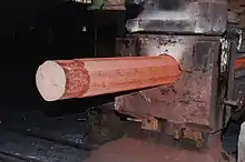
Open-die forging is also known as smith forging.[9] In open-die forging, a hammer strikes and deforms the workpiece, which is placed on a stationary anvil. Open-die forging gets its name from the fact that the dies (the surfaces that are in contact with the workpiece) do not enclose the workpiece, allowing it to flow except where contacted by the dies. The operator therefore needs to orient and position the workpiece to get the desired shape. The dies are usually flat in shape, but some have a specially shaped surface for specialized operations. For example, a die may have a round, concave, or convex surface or be a tool to form holes or be a cut-off tool.[10] Open-die forgings can be worked into shapes which include discs, hubs, blocks, shafts (including step shafts or with flanges), sleeves, cylinders, flats, hexes, rounds, plate, and some custom shapes.[11] Open-die forging lends itself to short runs and is appropriate for art smithing and custom work. In some cases, open-die forging may be employed to rough-shape ingots to prepare them for subsequent operations. Open-die forging may also orient the grain to increase strength in the required direction.[10]
Advantages of open-die forging
- Reduced chance of voids
- Better fatigue resistance
- Improved microstructure
- Continuous grain flow
- Finer grain size
- Greater strength[12]
- Better response to thermal treatment [13]
- Improvement of internal quality
- Greater reliability of mechanical properties, ductility and impact resistance
"Cogging" is the successive deformation of a bar along its length using an open-die drop forge. It is commonly used to work a piece of raw material to the proper thickness. Once the proper thickness is achieved the proper width is achieved via "edging".[14] "Edging" is the process of concentrating material using a concave shaped open-die. The process is called "edging" because it is usually carried out on the ends of the workpiece. "Fullering" is a similar process that thins out sections of the forging using a convex shaped die. These processes prepare the workpieces for further forging processes.[15]
 Edging
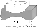 Fullering
Impression-die forging
Impression-die forging is also called "closed-die forging". In impression-die forging, the metal is placed in a die resembling a mold, which is attached to an anvil. Usually, the hammer die is shaped as well. The hammer is then dropped on the workpiece, causing the metal to flow and fill the die cavities. The hammer is generally in contact with the workpiece on the scale of milliseconds. Depending on the size and complexity of the part, the hammer may be dropped multiple times in quick succession. Excess metal is squeezed out of the die cavities, forming what is referred to as "flash". The flash cools more rapidly than the rest of the material; this cool metal is stronger than the metal in the die, so it helps prevent more flash from forming. This also forces the metal to completely fill the die cavity. After forging, the flash is removed.[9][16]
In commercial impression-die forging, the workpiece is usually moved through a series of cavities in a die to get from an ingot to the final form. The first impression is used to distribute the metal into the rough shape in accordance to the needs of later cavities; this impression is called an "edging", "fullering", or "bending" impression. The following cavities are called "blocking" cavities, in which the piece is working into a shape that more closely resembles the final product. These stages usually impart the workpiece with generous bends and large fillets. The final shape is forged in a "final" or "finisher" impression cavity. If there is only a short run of parts to be done, then it may be more economical for the die to lack a final impression cavity and instead machine the final features.[4]
Impression-die forging has been improved in recent years through increased automation which includes induction heating, mechanical feeding, positioning and manipulation, and the direct heat treatment of parts after forging.[17] One variation of impression-die forging is called "flashless forging", or "true closed-die forging". In this type of forging, the die cavities are completely closed, which keeps the workpiece from forming flash. The major advantage to this process is that less metal is lost to flash. Flash can account for 20 to 45% of the starting material. The disadvantages of this process include additional cost due to a more complex die design and the need for better lubrication and workpiece placement.[4]
There are other variations of part formation that integrate impression-die forging. One method incorporates casting a forging preform from liquid metal. The casting is removed after it has solidified, but while still hot. It is then finished in a single cavity die. The flash is trimmed, then the part is quench hardened. Another variation follows the same process as outlined above, except the preform is produced by the spraying deposition of metal droplets into shaped collectors (similar to the Osprey process).[17]
Closed-die forging has a high initial cost due to the creation of dies and required design work to make working die cavities. However, it has low recurring costs for each part, thus forgings become more economical with greater production volume. This is one of the major reasons closed-die forgings are often used in the automotive and tool industries. Another reason forgings are common in these industrial sectors is that forgings generally have about a 20 percent higher strength-to-weight ratio compared to cast or machined parts of the same material.[4]
Design of impression-die forgings and tooling
Forging dies are usually made of high-alloy or tool steel. Dies must be impact- and wear-resistant, maintain strength at high temperatures, have the ability to withstand cycles of rapid heating and cooling. In order to produce a better, more economical die the following standards are maintained:[17]
- The dies part along a single, flat plane whenever possible. If not, the parting plane follows the contour of the part.
- The parting surface is a plane through the center of the forging and not near an upper or lower edge.
- Adequate draft is provided; usually at least 3° for aluminium and 5° to 7° for steel.
- Generous fillets and radii are used.
- Ribs are low and wide.
- The various sections are balanced to avoid extreme difference in metal flow.
- Full advantage is taken of fiber flow lines.
- Dimensional tolerances are not closer than necessary.
Barrelling occurs when, due to friction between the work piece and the die or punch, the work piece bulges at its centre in such a way as to resemble a barrel. This leads to the central part of the work piece to come in contact with the sides of the die sooner than if there were no friction present, creating a much greater increase in the pressure required for the punch to finish the forging.
The dimensional tolerances of a steel part produced using the impression-die forging method are outlined in the table below. The dimensions across the parting plane are affected by the closure of the dies, and are therefore dependent on die wear and the thickness of the final flash. Dimensions that are completely contained within a single die segment or half can be maintained at a significantly greater level of accuracy.[16]
| Mass [kg (lb)] | Minus tolerance [mm (in)] | Plus tolerance [mm (in)] |
|---|---|---|
| 0.45 (1) | 0.15 (0.006) | 0.46 (0.018) |
| 0.91 (2) | 0.20 (0.008) | 0.61 (0.024) |
| 2.27 (5) | 0.25 (0.010) | 0.76 (0.030) |
| 4.54 (10) | 0.28 (0.011) | 0.84 (0.033) |
| 9.07 (20) | 0.33 (0.013) | 0.99 (0.039) |
| 22.68 (50) | 0.48 (0.019) | 1.45 (0.057) |
| 45.36 (100) | 0.74 (0.029) | 2.21 (0.087) |
A lubricant is used when forging to reduce friction and wear. It is also used as a thermal barrier to restrict heat transfer from the workpiece to the die. Finally, the lubricant acts as a parting compound to prevent the part from sticking in the dies.[16]
Press forging
Press forging works by slowly applying a continuous pressure or force, which differs from the near-instantaneous impact of drop-hammer forging. The amount of time the dies are in contact with the workpiece is measured in seconds (as compared to the milliseconds of drop-hammer forges). The press forging operation can be done either cold or hot.[16]
The main advantage of press forging, as compared to drop-hammer forging, is its ability to deform the complete workpiece. Drop-hammer forging usually only deforms the surfaces of the work piece in contact with the hammer and anvil; the interior of the workpiece will stay relatively undeformed. Another advantage to the process includes the knowledge of the new part's strain rate. By controlling the compression rate of the press forging operation, the internal strain can be controlled.
There are a few disadvantages to this process, most stemming from the workpiece being in contact with the dies for such an extended period of time. The operation is a time-consuming process due to the amount and length of steps. The workpiece will cool faster because the dies are in contact with workpiece; the dies facilitate drastically more heat transfer than the surrounding atmosphere. As the workpiece cools it becomes stronger and less ductile, which may induce cracking if deformation continues. Therefore, heated dies are usually used to reduce heat loss, promote surface flow, and enable the production of finer details and closer tolerances. The workpiece may also need to be reheated.
When done in high productivity, press forging is more economical than hammer forging. The operation also creates closer tolerances. In hammer forging a lot of the work is absorbed by the machinery; when in press forging, the greater percentage of work is used in the work piece. Another advantage is that the operation can be used to create any size part because there is no limit to the size of the press forging machine. New press forging techniques have been able to create a higher degree of mechanical and orientation integrity. By the constraint of oxidation to the outer layers of the part, reduced levels of microcracking occur in the finished part.[16]
Press forging can be used to perform all types of forging, including open-die and impression-die forging. Impression-die press forging usually requires less draft than drop forging and has better dimensional accuracy. Also, press forgings can often be done in one closing of the dies, allowing for easy automation.[18]
Upset forging
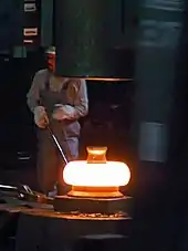
Upset forging increases the diameter of the workpiece by compressing its length.[18] Based on number of pieces produced, this is the most widely used forging process.[18] A few examples of common parts produced using the upset forging process are engine valves, couplings, bolts, screws, and other fasteners.
Upset forging is usually done in special high-speed machines called crank presses. The machines are usually set up to work in the horizontal plane, to facilitate the quick exchange of workpieces from one station to the next, but upsetting can also be done in a vertical crank press or a hydraulic press. The initial workpiece is usually wire or rod, but some machines can accept bars up to 25 cm (9.8 in) in diameter and a capacity of over 1000 tons. The standard upsetting machine employs split dies that contain multiple cavities. The dies open enough to allow the workpiece to move from one cavity to the next; the dies then close and the heading tool, or ram, then moves longitudinally against the bar, upsetting it into the cavity. If all of the cavities are utilized on every cycle, then a finished part will be produced with every cycle, which makes this process advantageous for mass production.[18]
These rules must be followed when designing parts to be upset forged:[19]
- The length of unsupported metal that can be upset in one blow without injurious buckling should be limited to three times the diameter of the bar.
- Lengths of stock greater than three times the diameter may be upset successfully, provided that the diameter of the upset is not more than 1.5 times the diameter of the stock.
- In an upset requiring stock length greater than three times the diameter of the stock, and where the diameter of the cavity is not more than 1.5 times the diameter of the stock, the length of unsupported metal beyond the face of the die must not exceed the diameter of the bar.
Automatic hot forging
The automatic hot forging process involves feeding mill-length steel bars (typically 7 m (23 ft) long) into one end of the machine at room temperature and hot forged products emerge from the other end. This all occurs rapidly; small parts can be made at a rate of 180 parts per minute (ppm) and larger can be made at a rate of 90 ppm. The parts can be solid or hollow, round or symmetrical, up to 6 kg (13 lb), and up to 18 cm (7.1 in) in diameter. The main advantages to this process are its high output rate and ability to accept low-cost materials. Little labor is required to operate the machinery.
There is no flash produced so material savings are between 20 and 30% over conventional forging. The final product is a consistent 1,050 °C (1,920 °F) so air cooling will result in a part that is still easily machinable (the advantage being the lack of annealing required after forging). Tolerances are usually ±0.3 mm (0.012 in), surfaces are clean, and draft angles are 0.5 to 1°. Tool life is nearly double that of conventional forging because contact times are on the order of 0.06-second. The downside is that this process is only feasible on smaller symmetric parts and cost; the initial investment can be over $10 million, so large quantities are required to justify this process.[20]
The process starts by heating the bar to 1,200 to 1,300 °C (2,190 to 2,370 °F) in less than 60 seconds using high-power induction coils. It is then descaled with rollers, sheared into blanks, and transferred through several successive forming stages, during which it is upset, preformed, final forged, and pierced (if necessary). This process can also be coupled with high-speed cold-forming operations. Generally, the cold forming operation will do the finishing stage so that the advantages of cold-working can be obtained, while maintaining the high speed of automatic hot forging.[21]
Examples of parts made by this process are: wheel hub unit bearings, transmission gears, tapered roller bearing races, stainless steel coupling flanges, and neck rings for LP gas cylinders.[22] Manual transmission gears are an example of automatic hot forging used in conjunction with cold working.[23]
Roll forging
Roll forging is a process where round or flat bar stock is reduced in thickness and increased in length. Roll forging is performed using two cylindrical or semi-cylindrical rolls, each containing one or more shaped grooves. A heated bar is inserted into the rolls and when it hits a spot the rolls rotate and the bar is progressively shaped as it is rolled through the machine. The piece is then transferred to the next set of grooves or turned around and reinserted into the same grooves. This continues until the desired shape and size is achieved. The advantage of this process is there is no flash and it imparts a favorable grain structure into the workpiece.[24]
Examples of products produced using this method include axles, tapered levers and leaf springs.
Net-shape and near-net-shape forging
This process is also known as precision forging. It was developed to minimize cost and waste associated with post-forging operations. Therefore, the final product from a precision forging needs little or no final machining. Cost savings are gained from the use of less material, and thus less scrap, the overall decrease in energy used, and the reduction or elimination of machining. Precision forging also requires less of a draft, 1° to 0°. The downside of this process is its cost, therefore it is only implemented if significant cost reduction can be achieved.[25]
Cold forging
Near net shape forging is most common when parts are forged without heating the slug, bar or billet. Aluminum is a common material that can be cold forged depending on final shape. Lubrication of the parts being formed is critical to increase the life of the mating dies.
Induction forging
Unlike the above processes, induction forging is based on the type of heating style used. Many of the above processes can be used in conjunction with this heating method.
Multidirectional forging
Multidirectional Forging is forming of a work piece in a single step in several directions. The multidirectional forming takes place through constructive measures of the tool. The vertical movement of the press ram is redirected using wedges which distributes and redirects the force of the forging press in horizontal directions.[26]
Isothermal forging
Isothermal forging is a process by which the materials and the die are heated to the same temperature (iso- meaning "equal"). Adiabatic heating is used to assist in the deformation of the material, meaning the strain rates are highly controlled. Commonly used for forging aluminium, which has a lower forging temperature than steels. Forging temperatures for Aluminum are around 430 °C (806 °F), while steels and super alloys can be 930 to 1,260 °C (1,710 to 2,300 °F).
Benefits:
- Near net shapes which lead to lower machining requirements and therefore lower scrap rates
- Reproducibility of the part
- Due to the lower heat loss smaller machines can be used to make the forging
Disadvantages:
- Higher die material costs to handle temperatures and pressures
- Uniform heating systems are required
- Protective atmospheres or vacuum to reduce oxidation of the dies and material
- Low production rates
Materials and applications
Forging of steel
Depending on the forming temperature steel forging can be divided into:[27]
- Hot forging of steel
- Forging temperatures above the recrystallization temperature between 950–1250 °C
- Good formability
- Low forming forces
- Constant tensile strength of the workpieces
- Warm forging of steel
- Forging temperatures between 750–950 °C
- Less or no scaling at the workpiece surface
- Narrower tolerances achievable than in hot forging
- Limited formability and higher forming forces than for hot forging
- Lower forming forces than in cold forming
- Cold forging of steel
- Forging temperatures at room conditions, self-heating up to 150 °C due to the forming energy
- Narrowest tolerances achievable
- No scaling at workpiece surface
- Increase of strength and decrease of ductility due to strain hardening
- Low formability and high forming forces are necessary
For industrial processes steel alloys are primarily forged in hot condition. Brass, bronze, copper, precious metals and their alloys are manufactured by cold forging processes, while each metal requires a different forging temperature.
Forging of aluminium
- Aluminium forging is performed at a temperature range between 350–550 °C
- Forging temperatures above 550 °C are too close to the solidus temperature of the alloys and lead in conjunction with varying effective strains to unfavorable workpiece surfaces and potentially to a partial melting as well as fold formation.[28]
- Forging temperatures below 350 °C reduce formability by increasing the yield stress, which can lead to unfilled dies, cracking at the workpiece surface and increased die forces
Due to the narrow temperature range and high thermal conductivity, aluminium forging can only be realized in a particular process window. To provide good forming conditions a homogeneous temperature distribution in the entire workpiece is necessary. Therefore, the control of the tool temperature has a major influence to the process. For example, by optimizing the preform geometries the local effective strains can be influenced to reduce local overheating for a more homogeneous temperature distribution.[29]
Application of aluminium forged parts
High-strength aluminium alloys have the tensile strength of medium strong steel alloys while providing significant weight advantages. Therefore, aluminium forged parts are mainly used in aerospace, automotive industry and many other fields of engineering especially in those fields, where highest safety standards against failure by abuse, by shock or vibratory stresses are needed. Such parts are for example pistons, chassis parts, steering components and brake parts. Commonly used alloys are AlSi1MgMn (EN AW-6082) and AlZnMgCu1,5 (EN AW-7075). About 80% of all aluminium forged parts are made of AlSi1MgMn. The high-strength alloy AlZnMgCu1,5 is mainly used for aerospace applications.[30]
Forging of magnesium
- Magnesium forging occurs at a temperature range between 290–450 °C [31]
Magnesium alloys are more difficult to forge due to their low plasticity, low sensitivity to strain rates and narrow forming temperature.[32] Using semi-open die hot forging with a three-slide forging press (TSFP) has become a newly developed forging method for Mg-Al alloy AZ31, commonly used in forming aircraft brackets.[33] [34] This forging method has shown to improve tensile properties but lacks uniform grain size.[35] [36] Even though the application of magnesium alloys increases by 15-20% each year in the aerospace and automotive industry, forging magnesium alloys with specialized dies is expensive and an unfeasible method to produce parts for a mass market. Instead, most magnesium alloy parts for industry are produced by casting methods.
Equipment
The most common type of forging equipment is the hammer and anvil. Principles behind the hammer and anvil are still used today in drop-hammer equipment. The principle behind the machine is simple: raise the hammer and drop it or propel it into the workpiece, which rests on the anvil. The main variations between drop-hammers are in the way the hammer is powered; the most common being air and steam hammers. Drop-hammers usually operate in a vertical position. The main reason for this is excess energy (energy that isn't used to deform the workpiece) that isn't released as heat or sound needs to be transmitted to the foundation. Moreover, a large machine base is needed to absorb the impacts.[10]
To overcome some shortcomings of the drop-hammer, the counterblow machine or impactor is used. In a counterblow machine both the hammer and anvil move and the workpiece is held between them. Here excess energy becomes recoil. This allows the machine to work horizontally and have a smaller base. Other advantages include less noise, heat and vibration. It also produces a distinctly different flow pattern. Both of these machines can be used for open-die or closed-die forging.[37]
Forging presses
A forging press, often just called a press, is used for press forging. There are two main types: mechanical and hydraulic presses. Mechanical presses function by using cams, cranks and/or toggles to produce a preset (a predetermined force at a certain location in the stroke) and reproducible stroke. Due to the nature of this type of system, different forces are available at different stroke positions. Mechanical presses are faster than their hydraulic counterparts (up to 50 strokes per minute). Their capacities range from 3 to 160 MN (300 to 18,000 short tons-force). Hydraulic presses use fluid pressure and a piston to generate force. The advantages of a hydraulic press over a mechanical press are its flexibility and greater capacity. The disadvantages include a slower, larger, and costlier machine to operate.[16]
The roll forging, upsetting, and automatic hot forging processes all use specialized machinery.
| Force (tonnes) |
Ingot size (tonnes) |
Company | Location |
|---|---|---|---|
| 16,500 | 600 | Shanghai Electric Group[39] | Shanghai, China |
| 16,000 | 600 | China National Erzhong Group[39] | Deyang, China |
| 14,000 | 600 | Japan Steel Works | Japan |
| 15,000 | 580 | China First Heavy Industries Group[40] | Heilongjiang, China |
| 13,000 | Doosan | South Korea | |
| Force (tonnes) |
Force (tons) |
Ingot size (tonnes) |
Company | Location |
|---|---|---|---|---|
| 80,000 | (88,200) | >150 | China Erzhong[39] | Deyang, China |
| 75,000 | (82,690) | VSMPO-AVISMA | Russia | |
| 65,000 | (71,660) | Aubert & Duval[41][42] | Issoire, France | |
| 53,500 | (60,000) | Weber Metals, Inc.[43] | California, United States | |
| (45,350) | 50,000 | 20 | Alcoa,[44][45] Wyman Gordon[46][47] | USA |
| 40,000 | (44,100) | Aubert & Duval[41] | Pamiers, France | |
| 30,000 | (33,080) | 8 | Wyman Gordon[48] | Livingston, Scotland |
| 30,000 | (33,070) | Weber Metals, Inc.[49] | California, United States | |
| 30,000 | (33,070) | Howmet Aerospace[50] | Georgia, United States | |
References
- Degarmo, p. 389
- Heavy Manufacturing of Power Plants World Nuclear Association, September 2010. Retrieved: 25 September 2010.
- "Forging: The Early Years". All Metals & Forge Group. Retrieved 1 October 2013.
- Degarmo, p. 392
- http://www.scotforge.com/Why-Forging/Casting-Conversions
- "Types of Forging Processes".
- Degarmo, p. 373
- Degarmo, p. 375
- Degarmo, p. 391
- Degarmo, p. 390
- "Forging Shapes". All Metals & Forge Group. Retrieved 1 October 2013.
- "Forged Crankshaft Advantages". Great Lakes Forge. Retrieved 28 February 2014.
- "Advantages of Forging" (PDF). Frisa.
- Cast steel: Forging, archived from the original on 18 February 2009, retrieved 3 March 2010
- Kaushish, J. P. (2008), Manufacturing Processes, PHI Learning, p. 469, ISBN 978-81-203-3352-9
- Degarmo, p. 394
- Degarmo, p. 393
- Degarmo, p. 395
- Degarmo, pp. 395–396
- Degarmo, pp. 396–397
- Degarmo, p. 396
- Precision Hot Forging Archived 2008-10-20 at the Wayback Machine. Samtech. Retrieved 22 November 2007
- Precision Composite Forging Archived 2008-04-17 at the Wayback Machine. Samtech. Retrieved 22 November 2007
- Degarmo, pp. 397–398
- Degarmo, p. 398
- Behrens, Stonis, Rüther, Blohm: Flash reduced forging of complicated high duty parts using preforming operations, IPH - Institut für Integrierte Produktion Hannover gGmbH, Hannover, 2014.
- Doege, E., Behrens, B.-A.: Handbuch Umformtechnik: Grundlagen, Technologien, Maschinen (in German), Springer Verlag, 2010, p. 7
- Doege, E.; Behrens, B.-A.: Handbuch Umformtechnik: Grundlagen, Technologien, Maschinen, Springer Verlag, 2010, pp. 671f.
- Stonis, M.: Mehrdirektionales Schmieden von flachen Aluminiumlangteilen (in German), In: Behrens, B.-A.; Nyhuis, P.; Overmeyer, L. (ed.): Berichte aus dem IPH, Volume 01/2011, PZH Produktionstechnisches Zentrum GmbH, Garbsen 2011.
- Richter, J.; Stonis, M.: Qualitätsverbesserung beim Aluminiumschmieden (in German), In Aluminium Praxis, Giesel Verlag GmbH, Volume 20 (2015), Issue 6/15, p. 20.
- Papenberg, Nikolaus P et al. “Mg-Alloys for Forging Applications-A Review.” Materials (Basel, Switzerland) vol. 13,4 985. 22 Feb. 2020, doi:10.3390/ma13040985
- Papenberg, Nikolaus P et al. “Mg-Alloys for Forging Applications-A Review.” Materials (Basel, Switzerland) vol. 13,4 985. 22 Feb. 2020, doi:10.3390/ma13040985
- Dziubińska, A., Gontarz, A., Dziubiński, M., & Barszcz, M. (2016). THE FORMING OF MAGNESIUM ALLOY FORGINGS FOR AIRCRAFT AND AUTOMOTIVE APPLICATIONS. Advances in Science and Technology Research Journal. https://doi.org/10.12913/22998624/64003
- Dziubinska, A., & Gontarz, A. (2015). A new method for producing magnesium alloy twin-rib aircraft brackets. Aircraft Engineering and Aerospace Technology. https://doi.org/10.1108/AEAT-10-2013-0184
- Dziubinska, A., Gontarz, A., & Zagórski, I. (2018). Qualitative research on AZ31 magnesium alloy aircraft brackets with a triangular rib produced by a new forging method. Aircraft Engineering and Aerospace Technology. https://doi.org/10.1108/AEAT-09-2016-0160
- Dziubińska, A., Gontarz, A., Horzelska, K., & Pieśko, P. (2015). The Microstructure and Mechanical Properties of AZ31 Magnesium Alloy Aircraft Brackets Produced by a New Forging Technology. Procedia Manufacturing. https://doi.org/10.1016/j.promfg.2015.07.059
- Degarmo, pp. 392–393
- Kidd, Steve. New nuclear build – sufficient supply capability? Archived June 13, 2011, at the Wayback Machine Nuclear Engineering International, 3 March 2009. Retrieved: 25 September 2010
- "China Building World's Largest Press Forge". China Tech Gadget. 27 October 2011. Retrieved 12 February 2012.
- "World's Largest 15000MN hydraulic forging press". China Tech Gadget. 3 November 2011. Retrieved 15 May 2012.
- "Eramet alloys". Archived from the original on 10 December 2010. Retrieved 18 May 2012.
- Altan, Taylan (1983). Feasibility of Using a Large Press (80,000 – 200,000 Ton) for Manufacturing Future Components on Army Systems. p. 12.
- Dean M. Peters (10 December 2018). "Weber Metals' New 60,000-Ton Hydraulic Press". Forge Magazine. Retrieved 25 April 2020.
- Heffernan, Tim (8 February 2012). "Iron Giant". The Atlantic. Retrieved 12 February 2012.
- 50,000 Ton Closed Die Forging Press (PDF). American Society of Mechanical Engineers. 1981. Archived from the original (PDF) on 2012-02-27. Retrieved 2012-05-15. History of the Mesta Press at Alcoa
- The Wyman-Gordon 50,000 Ton Forging Press (PDF). American Society of Mechanical Engineers. 1983. Archived from the original (PDF) on 2015-02-01. History of the Loewy Press at Wyman-Gordon
- Edson, Peter (18 April 1952). "Revolutionary Metal Press Cuts Cost of Planes and Guns". Sarasota Journal. Retrieved 12 February 2012.
- "Wyman Gordon Livingston". Retrieved 18 May 2012.
- "Weber Metals". Retrieved 18 July 2013.
- "Howmet Aerospace". Retrieved 18 May 2012.
Bibliography
- Degarmo, E. Paul; Black, J. T.; Kohser, Ronald A. (2011). Materials and Processes in Manufacturing (11th ed.). Wiley. ISBN 978-0-470-92467-9.
- Doege, E.; Behrens, B.-A.: Handbuch Umformtechnik: Grundlagen, Technologien, Maschinen (in German), 2nd Edition, Springer Verlag, 2010, ISBN 978-3-642-04248-5
- Ostermann, F.: Anwendungstechnologie Aluminium (in German), 3rd Edition, Springer Verlag, 2014, ISBN 978-3-662-43806-0
External links
| Wikimedia Commons has media related to Forging. |
