Venturi scrubber
A venturi scrubber is designed to effectively use the energy from a high-velocity inlet gas stream to atomize the liquid being used to scrub the gas stream. This type of technology is a part of the group of air pollution controls collectively referred to as wet scrubbers.
Venturis can be used to collect both particulate and gaseous pollutants, but although the liquid surface area provided is quite large they are more effective in removing particles since particles can be trapped by contact, but gases must be trapped by absorption during the relatively short exposure time.
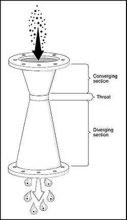
Venturi devices have also been used for over 100 years to measure fluid flow (Venturi tubes derived their name from Giovanni Battista Venturi, an Italian physicist). In the late 1940s, H.F. Johnstone[1], William Jones,[2] and other researchers found that they could effectively use the venturi configuration to remove particles from gas streams. Figure 1 illustrates the classic venturi configuration.[3]
Operation
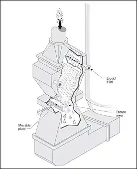
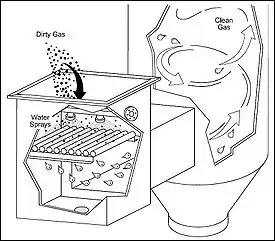
A venturi scrubber consists of three sections: a converging section, a throat section, and a diverging section. The inlet gas stream enters the converging section and, as the area decreases, gas velocity increases. Liquid is introduced either at the throat or at the entrance to the converging section. The inlet gas, forced to move at extremely high velocities in the small throat section, turbulently mixes with the liquid, producing an enormous number of very tiny droplets. Particle and gas removal occur in the diverging section as the inlet gas stream mixes with the fog of tiny liquid droplets. The inlet stream then exits through the diverging section, where it is forced to slow down.
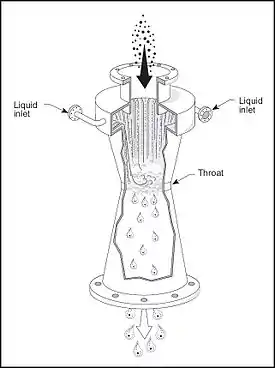
If liquid is introduced above the converging section and coats the walls up to the throat, then the venturi is described as having a "wet wall" or "wetted throat" as seen in Figure 2. This method allows particulates in the stream that may be prone to caking onto surfaces to be washed away and reduces the mechanical abrasion of particles hitting the throat at high speed. It very effective for handling hot, dry inlet gases that contain dust, or particles which are abrasive or corrosive, such as kiln or furnace gasses.
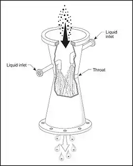
Wetting of the throat can be achieved with a spray directed at the walls or with a weir encircling the converging section which water flows over. This method can be used only at liquid injection source as the high velocity gas will shear droplets from the walls. Liquid can also be introduced by spray nozzles directly into the gas stream and for low gas flow velocities this may provide more efficient operation, either or both methods may be employed depending on the application.
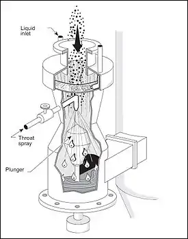
Simple venturis have fixed throat areas and so will only operate efficiently over a certain range of flow rates. Adjustable-throat venturis allow efficiency to be maintained over a much larger range of flows by changing the size of the throat in accordance with the gas flow rate. Certain types of orifices (throat areas) that create more turbulence than a true venturi were found to be equally efficient for a given unit of energy consumed and the results of these findings led to the development of the annular-orifice, or adjustable-throat, venturi scrubber (Figure 5).[3] The size of the throat area is varied by moving a plunger, or adjustable disk, up or down in the throat, thereby decreasing or increasing the annular opening. Gas flows through the annular opening and atomizes liquid that is sprayed onto the plunger or swirled in from the top.
Wetted-throat venturis with round throats (Figures 2 and 3) can handle inlet flows as large as 88,000 m3/h (40,000 cfm) (Brady and Legatski 1977). At inlet flow rates greater than this, achieving uniform liquid distribution is difficult, unless additional weirs or baffles are used. To handle large inlet flows, scrubbers designed with long, narrow, rectangular throats (Figure 4) have been used.[3] The rectangular-throat venturi is often built to be adjustable by introducing moving plates or flaps into the throat, as shown in Figure 6. A water-wash spray is used to continually wash collected material from the plate.
Another modification can be seen in the venturi-rod or rod deck scrubber. By placing a number of pipes parallel to each other, a series of longitudinal venturi openings can be created as shown in Figure 7.[3] The area between adjacent rods is a small venturi throat. Water sprays help prevent solids buildup. The principal atomization of the liquid occurs at the rods, where the high-velocity gas moving through spacings creates the small droplets necessary for fine particle collection. This method can produce very high water droplet densities in the gas stream due to a very high throat perimeter compared to other types. These rods must be made of abrasion-resistant material due to the high velocities present.

All venturi scrubbers require an entrainment separator because the high velocity of gas through the scrubber will have a tendency to entrain the droplets with the outlet clean gas stream. Cyclonic, mesh-pad, and blade separators are all used to remove liquid droplets from the flue gas and return the liquid to the scrubber water.
Ejector venturi scrubber
An ejector venturi scrubber switches the source of the mixing energy from the gas stream to the scrubbing liquid. In this setup the liquid may be sprayed at a high enough velocity and volume to draw the process gas through the device without external assistance.
Particle collection
The atomized liquid provides an enormous number of tiny droplets for the dust particles to impact on. These liquid droplets incorporating the particles must be removed from the scrubber outlet stream, generally by cyclonic separators.
Particle removal efficiency increases with increasing pressure drop because of increased turbulence due to high gas velocity in the throat. Venturis can be operated with pressure drops ranging from 12millibar to 250millibar.
Most venturis normally operate with pressure drops in the range of 50 to 150 cm (20 to 60 in) of water. At these pressure drops, the gas velocity in the throat section is usually between 30 and 120 m/s (100 to 400 ft/s), or approximately 270 mph at the high end. These high pressure drops result in high operating costs.
The liquid-injection rate, or liquid-to-gas ratio (L/G), also affects particle collection. The proper amount of liquid must be injected to provide adequate liquid coverage over the throat area and make up for any evaporation losses. If there is insufficient liquid, then there will not be enough liquid targets to provide the required capture efficiency.
Most venturi systems operate with an L/G ratio of 0.4 to 1.3 l/m3 (3 to 10 gal/1000 ft3) (Brady and Legatski 1977). L/G ratios less than 0.4 l/m3 (3 gal/1000 ft3) are usually not sufficient to cover the throat, and adding more than 1.3 l/m3 (10 gal/1000 ft3) does not usually significantly improve particle collection efficiency.
Gas collection
Venturi scrubbers can be used for removing gaseous pollutants; however, they are not used when removal of gaseous pollutants is the only concern.
The high inlet gas velocities in a venturi scrubber result in a very short contact time between the liquid and gas phases. This short contact time limits gas absorption. However, because venturis have a relatively open design compared to other scrubbers, they are still very useful for simultaneous gaseous and particulate pollutant removal, especially when:
- Scaling could be a problem
- A high concentration of dust is in the inlet stream
- The dust is sticky or has a tendency to plug openings
- The gaseous contaminant is very soluble or chemically reactive with the liquid
To maximize the absorption of gases, venturis are designed to operate at a different set of conditions from those used to collect particles. The gas velocities are lower and the liquid-to-gas ratios are higher for absorption.
For a given venturi design, if the gas velocity is decreased, then the pressure drop (resistance to flow) will also decrease and vice versa. Therefore, by reducing pressure drop, the gas velocity is decreased and the corresponding residence time is increased. Liquid-to-gas ratios for these gas absorption applications are approximately 2.7 to 5.3 l/m3 (20 to 40 gal/1000 ft3). The reduction in gas velocity allows for a longer contact time between phases and better absorption.
Increasing the liquid-to-gas ratio will increase the potential solubility of the pollutant in the liquid. This is why the ejector venturi scrubber is often used instead for this purpose, although other factors may still result in a typical venturi scrubber being chosen.
Though capable of some incidental control of volatile organic compounds (VOC), generally venturi scrubbers are limited to control PM (particulate matter) and high solubility or reactive gases (EPA, 1992; EPA, 1996).[4]
Maintenance considerations
The primary maintenance problem for venturi scrubbers is wear, or abrasion, of the scrubber shell because of high gas velocities. Gas velocities in the throat can reach speeds of 430 km/h (270 mph). Particles and liquid droplets traveling at these speeds can rapidly erode the scrubber shell.
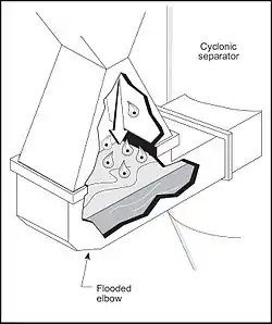
Abrasion can be reduced by lining the throat with silicon carbide brick or fitting it with a replaceable liner. Abrasion can also occur downstream of the throat section. To reduce abrasion here, the elbow at the bottom of the scrubber (leading into the separator) can be flooded (i.e. filled with a pool of scrubbing liquid). Particles and droplets impact on the pool of liquid, reducing wear on the scrubber shell.
A common technique to help reduce abrasion is to use a precleaner (i.e., quench sprays or cyclone) to remove the larger and more damaging particles. This also has the added benefit reducing the particle load carried by the liquid.
The method of liquid injection at the venturi throat can also cause problems. Spray nozzles are used for liquid distribution because they are more efficient (have a more effective spray pattern) for liquid injection than weirs. However, spray nozzles can easily plug when liquid is recirculated. Automatic or manual reamers can be used to correct this problem. However, when heavy liquid slurries (either viscous or particle-loaded) are recirculated, open-weir injection is often necessary.
Summary
Venturi scrubbers can have the highest particle collection efficiencies (especially for very small particles) of any wet scrubbing system.
They are the most widely used scrubbers because their open construction enables them to remove most particles without plugging or scalding. Venturis can also be used to absorb pollutant gases; however, they are not as efficient for this as are packed or plate towers.
Venturi scrubbers have been designed to collect particles at very high collection efficiencies, sometimes exceeding 99%. The ability of venturis to handle large inlet volumes at high temperatures makes them very attractive to many industries; consequently, they are used to reduce particulate emissions in a number of industrial applications. This ability is particularly desirable for cement kiln emission reduction and for control of emissions from basic oxygen furnaces in the steel industry, where the inlet gas enters the scrubber at temperatures greater than 350 °C (660 °F).
Venturis are also used to control fly ash and sulfur dioxide emissions from industrial and utility boilers.
The operating characteristics of venturi scrubbers are listed in Table 1.[3]
| Table 1. Operating characteristics of venturi scrubbers | |||||
|---|---|---|---|---|---|
| Pollutant | Pressure drop (Δp) | Liquid-to-gas ratio (L/G) | Liquid-inlet pressure (pL) | Removal efficiency | |
| Gases | 13–250 cm of water (5-100 in of water) | 2.7-5.3 l/m3 (20-40 gal/1,000 ft3) | < 7-100 kPa (< 1-15 psig) | 30-60% per venturi, depending on pollutant solubility | |
| Particles | 50–250 cm of water (50–150 cm of water is common) 20-100 in of water (20-60 in. of water is common) |
0.67-1.34 l/m3(5-10 gal/1,000 ft3) | 90-99% is typical | ||
Bibliography
- Anderson 2000 Company. Venturi scrubbing equipment. Engineering Manual with Operating and Maintenance Instructions. Atlanta: Anderson Company.
- Bethea, R. M. 1978. Air Pollution Control Technology. New York: Van Nostrand Reinhold.
- Brady, J. D., and L. K. Legatski. 1977. Venturi scrubbers. In P. N. Cheremisinoff and R. A. Young (Eds.), Air Pollution Control and Design Handbook. Part 2. New York: Marcel Dekker.
- Buonicore, A. J. 1982. Wet scrubbers. In L. Theodore and A. J. Buonicore (Eds.), Air Pollution Control Equipment, Design, Selection, Operation and Maintenance. Englewood Cliffs: Prentice-Hall.
- Calvert, S. 1977. How to choose a particulate scrubber. Chemical Engineering. 84:133-140.
- Johnstone, H. F., and M. H. Roberts. 1949. Deposition of aerosol particles from moving gas streams. Industrial and Engineering Chemistry. 41:2417-2423.
- Kelly, J. W. 1978, December 4. Maintaining venturi-tray scrubbers. Chemical Engineering.
- McIlvaine Company. 1974. The Wet Scrubber Handbook. Northbrook, IL: McIlvaine Company.
- Richards, J. R. 1995. Control of Particulate Emissions (APTI Course 413). U.S. Environmental Protection Agency.
- Richards, J. R. 1995. Control of Gaseous Emissions. (APTI Course 415). U.S. Environmental Protection Agency.
See also
External links
- Air Pollution Training Courses (from website of U.S. EPA's Air Pollution Training Institute)
References
- Johnstone, H. F.; Roberts, M. N. (1949-11-01). "Deposition of Aerosol Particles from Moving Gas Streams". Industrial & Engineering Chemistry. 41 (11): 2417–2423. doi:10.1021/ie50479a019. ISSN 0019-7866.
- Jones, William P. (1949-11-05). "Development of the Venturi Scrubber". Industrial & Engineering Chemistry. 41 (11): 2424–2427. doi:10.1021/ie50479a020. ISSN 0019-7866.
- Course SI 412C: Lesson 3 U.S. EPA Air Pollution Training Institute in collaboration with North Carolina State University, College of Engineering (NCSU)
- US EPA Clean Air Technology Center