Centrifugal clutch
A centrifugal clutch is an automatic clutch that uses centrifugal force to operate. The output shaft is disengaged at low rotational speed and engages more as speed increases. It is often used in mopeds, underbones, lawn mowers, go-karts, chainsaws, mini bikes, and some paramotors and boats to keep the engine from stalling when the output shaft is slowed or stopped abruptly, and to remove load when starting and idling. It has been superseded for automotive applications by the fluid coupling.
.jpg.webp)
Operation
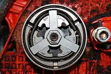
The input of the clutch is connected to the engine crankshaft while the output may drive a shaft, chain, or belt. As engine revolutions per minute increase, weighted arms in the clutch swing outward and force the clutch to engage. The most common types have friction pads or shoes radially mounted that engage the inside of the rim of a housing. On the center shaft, there is an assorted number of extension springs, which connect to a clutch shoe. When the central shaft spins fast enough, the springs extend causing the clutch shoes to engage the friction face. It can be compared to a drum brake in reverse. This type can be found on most home-built karts, lawn and garden equipment, fuel-powered model cars, and low power chainsaws.
Another type used in racing karts has friction and clutch disks stacked together like a motorcycle clutch. The weighted arms force these disks together and engage the clutch. When the engine reaches a certain speed, the clutch activates, working somewhat like a continuously variable transmission. As the load increases, the speed drops, disengaging the clutch, letting the speed rise again, and reengaging the clutch. If tuned properly, the clutch will tend to keep the speed at or near the torque peak of the engine. This results in a fair bit of waste heat, but over a broad range of speeds, it is much more useful than a direct drive in many applications.
History
Centrifugal clutches were used in railway locomotives before 1858,[1] and referred to (in relation to electric motors) in a patent of 1899.[2]
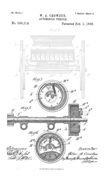
A patent was issued in the United States for an automotive centrifugal clutch (on an electric vehicle) in 1898.[3]
There is a design for a toy 'automatic clutch' in Meccano Magazine of June 1934.[4]
Armstrong Siddeley cars featured automatic (centrifugal) clutches beginning in 1936.[5]
Thomas Fogarty, who is also credited with inventing the balloon catheter, is credited with inventing a centrifugal clutch for small motor applications in the 1940s.[6]
See also
References
| Wikimedia Commons has media related to Centrifugal clutches. |
- Minutes of Proceedings of the Institution of Civil Engineers, Volume 17 (1858)
- Patents for Inventions (Patent Office, 1899)
- US patent US598314, W A Crowdus, "AUTOMOBILE VEHICLE", issued 1898-02-01
- "Automatic Clutch". nzmeccano.com. Meccano Ltd. June 1934. Retrieved September 8, 2019.
- "Armstrong Siddeley 17 HP". siddeley.com. Archived from the original on 2013-06-19.
- "Thomas Fogarty Lemelson-MIT Program". lemelson.mit.edu. Retrieved 2019-01-30.
External links
- Compliant Centrifugal Clutches: Design, Analysis, and Testing, Master's thesis at the Harold B. Lee Library, Brigham Young University