Crankshaft
A crankshaft is a shaft driven by a crank mechanism, consisting of a series of cranks and crankpins to which the connecting rods of an engine are attached.[1] It is a mechanical part able to perform a conversion between reciprocating motion and rotational motion. In a reciprocating engine, it translates reciprocating motion of the piston into rotational motion, whereas in a reciprocating compressor, it converts the rotational motion into reciprocating motion. In order to do the conversion between two motions, the crankshaft has "crank throws" or "crankpins", additional bearing surfaces whose axis is offset from that of the crank, to which the "big ends" of the connecting rods from each cylinder attach.

It is typically connected to a flywheel to reduce the pulsation characteristic of the four-stroke cycle, and sometimes a torsional or vibrational damper at the opposite end, to reduce the torsional vibrations often caused along the length of the crankshaft by the cylinders farthest from the output end acting on the torsional elasticity of the metal.
History
Crank mechanism
Han China
The earliest hand-operated cranks appeared in China during the Han Dynasty (202 BC-220 AD). They were used for silk-reeling, hemp-spinning, for the agricultural winnowing fan, in the water-powered flour-sifter, for hydraulic-powered metallurgic bellows, and in the well windlass.[4] The rotary winnowing fan greatly increased the efficiency of separating grain from husks and stalks.[5][6] However, the potential of the crank of converting circular motion into reciprocal motion never seems to have been fully realized in China, and the crank was typically absent from such machines until the turn of the 20th century.[7]
Roman Empire
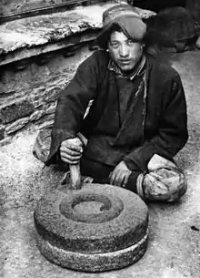
A crank in the form of an eccentrically-mounted handle of the rotary handmill appeared in 5th century BC Celtiberian Spain and ultimately spread across the Roman Empire.[8][2][3] A Roman iron crank dating to the 2nd century AD was excavated in Augusta Raurica, Switzerland.[9][10] The crank-operated Roman mill is dated to the late 2nd century.[11]
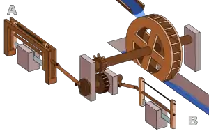
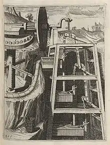
Evidence for the crank combined with a connecting rod appears in the Hierapolis mill, dating to the 3rd century; they are also found in stone sawmills in Roman Syria and Ephesus dating to the 6th century.[12] The pediment of the Hierapolis mill shows a waterwheel fed by a mill race powering via a gear train two frame saws which cut blocks by the way of some kind of connecting rods and cranks.[13] The crank and connecting rod mechanisms of the other two archaeologically-attested sawmills worked without a gear train.[14][15] Water-powered marble saws in Germany were mentioned by the late 4th century poet Ausonius;[12] about the same time, these mill types seem also to be indicated by Gregory of Nyssa from Anatolia.[16][12][17]
Medieval Europe
A rotary grindstone[18] operated by a crank handle is shown in the Carolingian manuscript Utrecht Psalter; the pen drawing of around 830 goes back to a late antique original.[19] Cranks used to turn wheels are also depicted or described in various works dating from the tenth to thirteenth centuries.[18][20]
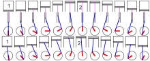
The first depictions of the compound crank in the carpenter's brace appear between 1420 and 1430 in northern European artwork.[21] The rapid adoption of the compound crank can be traced in the works of an unknown German engineer writing on the state of military technology during the Hussite Wars: first, the connecting-rod, applied to cranks, reappeared; second, double-compound cranks also began to be equipped with connecting-rods; and third, the flywheel was employed for these cranks to get them over the 'dead-spot'.[22] The concept was much improved by the Italian engineer and writer Roberto Valturio in 1463, who devised a boat with five sets, where the parallel cranks are all joined to a single power source by one connecting-rod, an idea also taken up by his compatriot Italian painter Francesco di Giorgio.[23]
The crank had become common in Europe by the early 15th century, as seen in the works of the military engineer Konrad Kyeser (1366–after 1405).[24][25] Devices depicted in Kyeser's Bellifortis include cranked windlasses for spanning siege crossbows, cranked chain of buckets for water-lifting and cranks fitted to a wheel of bells.[25] Kyeser also equipped the Archimedes' screws for water-raising with a crank handle, an innovation which subsequently replaced the ancient practice of working the pipe by treading.[26]
Pisanello painted a piston-pump driven by a water-wheel and operated by two simple cranks and two connecting-rods.[22]
The 15th also century saw the introduction of cranked rack-and-pinion devices, called cranequins, which were fitted to the crossbow's stock as a means of exerting even more force while spanning the missile weapon.[27] In the textile industry, cranked reels for winding skeins of yarn were introduced.[25]
Medieval Near East
The non-manual crank appears in several of the hydraulic devices described by the Banū Mūsā brothers in their 9th-century Book of Ingenious Devices.[28] These automatically operated cranks appear in several devices, two of which contain an action which approximates to that of a crankshaft, anticipating Al-Jazari's invention by several centuries and its first appearance in Europe by over five centuries. However, the automatic crank described by the Banu Musa would not have allowed a full rotation, but only a small modification was required to convert it to a crankshaft.[29]
Arab engineer Al-Jazari (1136–1206), in the Artuqid Sultanate, described a crank and connecting rod system in a rotating machine in two of his water-raising machines.[30] The author Sally Ganchy identified a crankshaft in his twin-cylinder pump mechanism,[31] including both the crank and shaft mechanisms.[32] According to historian Donald Routledge Hill, Al-Jazari invented the crankshaft.[29]
Renaissance Europe
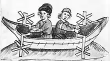
The Italian physician Guido da Vigevano (c. 1280−1349), planning for a new crusade, made illustrations for a paddle boat and war carriages that were propelled by manually turned compound cranks and gear wheels,[33] identified as an early crankshaft prototype by Lynn Townsend White.[34] The Luttrell Psalter, dating to around 1340, describes a grindstone which was rotated by two cranks, one at each end of its axle; the geared hand-mill, operated either with one or two cranks, appeared later in the 15th century.[25]
Around 1480, the early medieval rotary grindstone was improved with a treadle and crank mechanism. Cranks mounted on push-carts first appear in a German engraving of 1589.[35] Crankshafts were also described by Leonardo da Vinci (1452–1519)[30] and a Dutch farmer and windmill owner by the name Cornelis Corneliszoon van Uitgeest in 1592. His wind-powered sawmill used a crankshaft to convert a windmill's circular motion into a back-and-forward motion powering the saw. Corneliszoon was granted a patent for his crankshaft in 1597.
Modern Europe
From the 16th century onwards, evidence of cranks and connecting rods integrated into machine design becomes abundant in the technological treatises of the period: Agostino Ramelli's The Diverse and Artifactitious Machines of 1588 depicts eighteen examples, a number that rises in the Theatrum Machinarum Novum by Georg Andreas Böckler to 45 different machines.[36] Cranks were formerly common on some machines in the early 20th century; for example almost all phonographs before the 1930s were powered by clockwork motors wound with cranks. Reciprocating piston engines use cranks to convert the linear piston motion into rotational motion. Internal combustion engines of early 20th century automobiles were usually started with hand cranks, before electric starters came into general use. The 1918 Reo owner's manual describes how to hand crank the automobile:
- First: Make sure the gear shifting lever is in neutral position.
- Second: The clutch pedal is unlatched and the clutch engaged. The brake pedal is pushed forward as far as possible setting brakes on the rear wheel.
- Third: See that spark control lever, which is the short lever located on top of the steering wheel on the right side, is back as far as possible toward the driver and the long lever, on top of the steering column controlling the carburetor, is pushed forward about one inch from its retarded position.
- Fourth: Turn ignition switch to point marked "B" or "M"
- Fifth: Set the carburetor control on the steering column to the point marked "START." Be sure there is gasoline in the carburetor. Test for this by pressing down on the small pin projecting from the front of the bowl until the carburetor floods. If it fails to flood it shows that the fuel is not being delivered to the carburetor properly and the motor cannot be expected to start. See instructions on page 56 for filling the vacuum tank.
- Sixth: When it is certain the carburetor has a supply of fuel, grasp the handle of starting crank, push in endwise to engage ratchet with crank shaft pin and turn over the motor by giving a quick upward pull. Never push down, because if for any reason the motor should kick back, it would endanger the operator.
Internal combustion engines
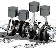

Large engines are usually multicylinder to reduce pulsations from individual firing strokes, with more than one piston attached to a complex crankshaft. Many small engines, such as those found in mopeds or garden machinery, are single cylinder and use only a single piston, simplifying crankshaft design.
A crankshaft is subjected to enormous stresses, potentially equivalent of several tonnes of force. The crankshaft is connected to the fly-wheel (used to smooth out shock and convert energy to torque), the engine block, using bearings on the main journals, and to the pistons via their respective con-rods. An engine loses up to 75% of its generated energy in the form of friction, noise and vibration in the crankcase and piston area.[37] The remaining losses occur in the valvetrain (timing chains, belts, pulleys, camshafts, lobes, valves, seals etc.) heat and blow by.
Bearings
The crankshaft has a linear axis about which it rotates, typically with several bearing journals riding on replaceable bearings (the main bearings) held in the engine block. As the crankshaft undergoes a great deal of sideways load from each cylinder in a multicylinder engine, it must be supported by several such bearings, not just one at each end. This was a factor in the rise of V8 engines, with their shorter crankshafts, in preference to straight-8 engines. The long crankshafts of the latter suffered from an unacceptable amount of flex when engine designers began using higher compression ratios and higher rotational speeds. High performance engines often have more main bearings than their lower performance cousins for this reason.
Piston stroke
The distance the axis of the crank throws from the axis of the crankshaft determines the piston stroke measurement, and thus engine displacement. A common way to increase the low-speed torque of an engine is to increase the stroke, sometimes known as "shaft-stroking." This also increases the reciprocating vibration, however, limiting the high speed capability of the engine. In compensation, it improves the low speed operation of the engine, as the longer intake stroke through smaller valve(s) results in greater turbulence and mixing of the intake charge. Most modern high speed production engines are classified as "over square" or short-stroke, wherein the stroke is less than the diameter of the cylinder bore. As such, finding the proper balance between shaft-stroking speed and length leads to better results.
Engine configuration
The configuration, meaning the number of pistons and their placement in relation to each other leads to straight, V or flat engines. The same basic engine block can sometimes be used with different crankshafts, however, to alter the firing order. For instance, the 90° V6 engine configuration, in older days sometimes derived by using six cylinders of a V8 engine with a 3 throw crankshaft, produces an engine with an inherent pulsation in the power flow due to the "gap" between the firing pulses alternates between short and long pauses because the 90 degree engine block does not correspond to the 120 degree spacing of the crankshaft. The same engine, however, can be made to provide evenly spaced power pulses by using a crankshaft with an individual crank throw for each cylinder, spaced so that the pistons are actually phased 120° apart, as in the GM 3800 engine. While most production V8 engines use four crank throws spaced 90° apart, high-performance V8 engines often use a "flat" crankshaft with throws spaced 180° apart, essentially resulting in two straight four engines running on a common crankcase. The difference can be heard as the flat-plane crankshafts result in the engine having a smoother, higher-pitched sound than cross-plane (for example, IRL IndyCar Series compared to NASCAR Sprint Cup Series, or a Ferrari 355 compared to a Chevrolet Corvette). This type of crankshaft was also used on early types of V8 engines. See the main article on crossplane crankshafts.
Engine balance
For some engines it is necessary to provide counterweights for the reciprocating mass of each piston and connecting rod to improve engine balance. These are typically cast as part of the crankshaft but, occasionally, are bolt-on pieces. While counter weights add a considerable amount of weight to the crankshaft, it provides a smoother running engine and allows higher RPM levels to be reached.
Flying arms

In some engine configurations, the crankshaft contains direct links between adjacent crank pins, without the usual intermediate main bearing. These links are called flying arms.[38] This arrangement is sometimes used in V6 and V8 engines, as it enables the engine to be designed with different V angles than what would otherwise be required to create an even firing interval, while still using fewer main bearings than would normally be required with a single piston per crankthrow. This arrangement reduces weight and engine length at the expense of less crankshaft rigidity.
Rotary aircraft engines
Some early aircraft engines were a rotary engine design, where the crankshaft was fixed to the airframe and instead the cylinders rotated with the propeller.
Radial engines
The radial engine is a reciprocating type internal combustion engine configuration in which the cylinders point outward from a central crankshaft like the spokes of a wheel. It resembles a stylized star when viewed from the front, and is called a "star engine" (German Sternmotor, French Moteur en étoile) in some languages. The radial configuration was very commonly used in aircraft engines before turbine engines became predominant.
Construction

Crankshafts can be monolithic (made in a single piece) or assembled from several pieces. Monolithic crankshafts are most common, but some smaller and larger engines use assembled crankshafts.
Forging and casting, and machining

Crankshafts can be forged from a steel bar usually through roll forging or cast in ductile steel. Today more and more manufacturers tend to favor the use of forged crankshafts due to their lighter weight, more compact dimensions and better inherent damping. With forged crankshafts, vanadium microalloyed steels are mostly used as these steels can be air cooled after reaching high strengths without additional heat treatment, with exception to the surface hardening of the bearing surfaces. The low alloy content also makes the material cheaper than high alloy steels. Carbon steels are also used, but these require additional heat treatment to reach the desired properties. Cast iron crankshafts are today mostly found in cheaper production engines (such as those found in the Ford Focus diesel engines) where the loads are lower. Some engines also use cast iron crankshafts for low output versions while the more expensive high output version use forged steel.
Crankshafts can also be machined out of a billet, often a bar of high quality vacuum remelted steel. Though the fiber flow (local inhomogeneities of the material's chemical composition generated during casting) does not follow the shape of the crankshaft (which is undesirable), this is usually not a problem since higher quality steels, which normally are difficult to forge, can be used. These crankshafts tend to be very expensive due to the large amount of material that must be removed with lathes and milling machines, the high material cost, and the additional heat treatment required. However, since no expensive tooling is needed, this production method allows small production runs without high costs.
In an effort to reduce costs, used crankshafts may also be machined. A good core may often be easily reconditioned by a crankshaft grinding [39] process. Severely damaged crankshafts may also be repaired with a welding operation, prior to grinding, that utilizes a submerged arc welding machine. To accommodate the smaller journal diameters a ground crankshaft has, and possibly an oversized thrust dimension, undersize engine bearings are used to allow for precise clearances during operation.
Machining or remanufacturing crankshafts are precision machined to exact tolerances with no odd size crankshaft bearings or journals. Thrust surfaces are micro-polished to provide precise surface finishes for smooth engine operation and reduced thrust bearing wear. Every journal is inspected and measured with critical accuracy. After machining, oil holes are chamfered to improve lubrication and every journal polished to a smooth finish for long bearing life. Remanufactured crankshafts are thoroughly cleaned with special emphasis to flushing and brushing out oil passages to remove any contaminants. Remanufacturing a crankshaft typically involves the following steps:[40]
Stress on crankshafts
The shaft is subjected to various forces but generally needs to be analysed in two positions. Firstly, failure may occur at the position of maximum bending; this may be at the centre of the crank or at either end. In such a condition the failure is due to bending and the pressure in the cylinder is maximal. Second, the crank may fail due to twisting, so the conrod needs to be checked for shear at the position of maximal twisting. The pressure at this position is the maximal pressure, but only a fraction of maximal pressure.
Counter-rotating crankshafts
In a conventional piston-crank arrangement in an engine or compressor, a piston is connected to a crankshaft by a connecting rod. As the piston moves through its stroke, the connecting rod varies its angle to the direction of motion of the piston and as the connecting rod is free to rotate at its connection to both the piston and crankshaft, no torque is transmitted by the connecting rod and forces transmitted by the connecting rod are transmitted along the longitudinal axis of the connecting rod. The force exerted by the piston on the connecting rod results in a reaction force exerted by the connecting rod back on the piston. When the connecting rod makes an angle to the direction of motion of the piston, the reaction force exerted by the connecting rod on the piston has a lateral component. This lateral force pushes the piston sideways against the cylinder wall. As the piston moves within the cylinder, this lateral force causes additional friction between the piston and cylinder wall. Friction accounts for approximately 20% of all losses in an internal combustion engine, of which approximately 50% is due to piston cylinder friction [41]
In a paired counter-rotating crankshaft arrangement, each piston is connected to two crankshafts so lateral forces due to the angle of the connecting rods cancel each other out. This reduces piston-cylinder friction and therefore fuel consumption. The symmetrical arrangement reduces the requirement for counterweights, reducing overall mass and making it easier for the engine to accelerate and decelerate. It also eliminates engine rocking and torque effects. Several counter-rotating crankshaft arrangements have been patented, for example US2010/0263621. An early example of a counter-rotating crankshaft arrangement is the Lanchester flat-twin engine.
See also
| Wikimedia Commons has media related to Crankshaft. |
- Bicycle crankset
- Brace (tool)
- Cam
- Camshaft
- Crankcase, the housing that surrounds the crankshaft
- Crankshaft torsional vibration
- Crank (mechanism)
- Hudson Motor Car Company, balanced crankshaft in 1916 allowed higher RPM & more power
- Piston motion equations
- Tunnel crankshaft
- Sun and planet gear
- Scotch yoke
- swashplate
- wobble plate
References
- "Definition of CRANKSHAFT". Merriam-Webster Dictionary.
- Ritti, Grewe & Kessener 2007, p. 159
- Lucas 2005, p. 5, fn. 9
- Needham 1986, pp. 118-119
- Bautista Paz, Emilio; Ceccarelli, Marco; Otero, Javier Echávarri; Sanz, José Luis Muñoz (2010). A Brief Illustrated History of Machines and Mechanisms. Springer (published May 12, 2010). p. 19. ISBN 978-9048125111.
- Du Bois, George (2014). Understanding China: Dangerous Resentments. Trafford on Demand. ISBN 978-1490745077.
- White, Jr. 1962, p. 104: Yet a student of the Chinese technology of the early twentieth century remarks that even a generation ago the Chinese had not 'reached that stage where continuous rotary motion is substituted for reciprocating motion in technical contrivances such as the drill, lathe, saw, etc. To take this step familiarity with the crank is necessary. The crank in its simple rudimentary form we find in the [modern] Chinese windlass, which use of the device, however, has apparently not given the impulse to change reciprocating into circular motion in other contrivances'. In China the crank was known, but remained dormant for at least nineteen centuries, its explosive potential for applied mechanics being unrecognized and unexploited.
- Frankel 2003, pp. 17–19
- Schiöler 2009, pp. 113f.
- Laur-Belart 1988, pp. 51–52, 56, fig. 42
- Volpert 1997, pp. 195, 199
- Ritti, Grewe & Kessener 2007, p. 161: Because of the findings at Ephesus and Gerasa the invention of the crank and connecting rod system has had to be redated from the 13th to the 6th c; now the Hierapolis relief takes it back another three centuries, which confirms that water-powered stone saw mills were indeed in use when Ausonius wrote his Mosella.
- Ritti, Grewe & Kessener 2007, pp. 139–141
- Ritti, Grewe & Kessener 2007, pp. 149–153
- Mangartz 2010, pp. 579f.
- Wilson 2002, p. 16
- Ritti, Grewe & Kessener 2007, p. 156, fn. 74
- White, Jr. 1962, p. 110
- Hägermann & Schneider 1997, pp. 425f.
- Needham 1986, pp. 112–113.
- White, Jr. 1962, p. 112
- White, Jr. 1962, p. 113
- White, Jr. 1962, p. 114
- Needham 1986, p. 113.
- White, Jr. 1962, p. 111
- White, Jr. 1962, pp. 105, 111, 168
- Hall 1979, pp. 74f.
- A. F. L. Beeston, M. J. L. Young, J. D. Latham, Robert Bertram Serjeant (1990), The Cambridge History of Arabic Literature, Cambridge University Press, p. 266, ISBN 0-521-32763-6
- Banu Musa (authors), Donald Routledge Hill (translator) (1979), The book of ingenious devices (Kitāb al-ḥiyal), Springer, pp. 23–4, ISBN 90-277-0833-9
- Ahmad Y Hassan. The Crank-Connecting Rod System in a Continuously Rotating Machine.
- Sally Ganchy, Sarah Gancher (2009), Islam and Science, Medicine, and Technology, The Rosen Publishing Group, p. 41, ISBN 978-1-4358-5066-8
- Donald Hill (2012), The Book of Knowledge of Ingenious Mechanical Devices, page 273, Springer Science + Business Media
- Hall 1979, p. 80
- Townsend White, Lynn (1978). Medieval Religion and Technology: Collected Essays. University of California Press. p. 335. ISBN 9780520035669.
- White, Jr. 1962, p. 167
- White, Jr. 1962, p. 172
- Ghimire, Arjun (2017). Basic Principles of Engineering. [Lulu.com]. p. 150. ISBN 9781387294992.
- Nunney 2007, pp. 16, 41.
- "Crankshaft Grinding". Crankshaft Repair.
- "Remanufactured Crankshafts - Capital Reman Exchange". Capital Reman Exchange. Retrieved 2015-12-28.
- Andersson BS (1991), Company's perspective in vehicle tribology. In: 18th Leeds-Lyon Symposium (eds D Dowson, CM Taylor and MGodet), Lyon, France, 3-6 September 1991, New York: Elsevier, pp. 503–506
Sources
- Frankel, Rafael (2003), "The Olynthus Mill, Its Origin, and Diffusion: Typology and Distribution", American Journal of Archaeology, 107 (1): 1–21, doi:10.3764/aja.107.1.1
- Hägermann, Dieter; Schneider, Helmuth (1997), Propyläen Technikgeschichte. Landbau und Handwerk, 750 v. Chr. bis 1000 n. Chr. (2nd ed.), Berlin, ISBN 3-549-05632-X
- Hall, Bert S. (1979), The Technological Illustrations of the So-Called "Anonymous of the Hussite Wars". Codex Latinus Monacensis 197, Part 1, Wiesbaden: Dr. Ludwig Reichert Verlag, ISBN 3-920153-93-6
- Laur-Belart, Rudolf (1988), Führer durch Augusta Raurica (5th ed.), Augst
- Lucas, Adam Robert (2005), "Industrial Milling in the Ancient and Medieval Worlds. A Survey of the Evidence for an Industrial Revolution in Medieval Europe", Technology and Culture, 46 (1): 1–30, doi:10.1353/tech.2005.0026
- Mangartz, Fritz (2010), Die byzantinische Steinsäge von Ephesos. Baubefund, Rekonstruktion, Architekturteile, Monographs of the RGZM, 86, Mainz: Römisch-Germanisches Zentralmuseum, ISBN 978-3-88467-149-8
- Needham, Joseph (1986), Science and Civilisation in China: Volume 4, Physics and Physical Technology: Part 2, Mechanical Engineering, Cambridge University Press, ISBN 0-521-05803-1
- Nunney, Malcolm J. (2007), Light and Heavy Vehicle Technology (4th ed.), Elsevier Butterworth-Heinemann, ISBN 978-0-7506-8037-0
- Ritti, Tullia; Grewe, Klaus; Kessener, Paul (2007), "A Relief of a Water-powered Stone Saw Mill on a Sarcophagus at Hierapolis and its Implications", Journal of Roman Archaeology, 20: 138–163, doi:10.1017/S1047759400005341
- Schiöler, Thorkild (2009), "Die Kurbelwelle von Augst und die römische Steinsägemühle", Helvetia Archaeologica, 40 (159/160), pp. 113–124
- Volpert, Hans-Peter (1997), "Eine römische Kurbelmühle aus Aschheim, Lkr. München", Bericht der Bayerischen Bodendenkmalpflege, 38: 193–199, ISBN 3-7749-2903-3
- White, Jr., Lynn (1962), Medieval Technology and Social Change, Oxford: At the Clarendon Press
- Wilson, Andrew (2002), "Machines, Power and the Ancient Economy", The Journal of Roman Studies, 92, pp. 1–32
External links
- Interactive crank animation https://www.desmos.com/calculator/8l2kvyivqo
- D & T Mechanisms - Interactive Tools for Teachers (applets) https://web.archive.org/web/20140714155346/http://www.content.networcs.net/tft/mechanisms.htm
- Grewe, Klaus (2009). "Die Reliefdarstellung einer antiken Steinsägemaschine aus Hierapolis in Phrygien und ihre Bedeutung für die Technikgeschichte. Internationale Konferenz 13.−16. Juni 2007 in Istanbul". In Bachmann, Martin (ed.). Bautechnik im antiken und vorantiken Kleinasien (PDF). Byzas (in German). 9. Istanbul: Ege Yayınları/Zero Prod. Ltd. pp. 429–454. ISBN 978-975-807-223-1. Archived from the original (PDF) on 2011-05-11.