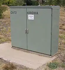
Digital loop carrier
A digital loop carrier (DLC) is a system which uses digital transmission to extend the range of the local loop farther than would be possible using only twisted pair copper wires. A DLC digitizes and multiplexes the individual signals carried by the local loops onto a single datastream on the DLC segment.

Reasons for using DLCs
Subscriber Loop Carrier systems address a number of problems:
- Electrical constraints on long loops.
- Insufficient available cable pairs.
- Cable route congestion (inability to add cable due to lack of space, particularly in urban street, bridge, and building conduit)
- Construction challenges (in areas of difficult terrain) when limited cable pairs are already available
- Expense due to cable cost and the associated labour-intensive installation work (especially to solve the specific problems listed above)
Long loops, such as those terminating at more than 18,000 feet (5.49 kilometres) from the central office, pose electrical challenges. When the subscriber goes off-hook, a cable pair behaves like a single loop inductance coil with a -48 V dc potential and an Electric current of between 20–50 mA dc. Electric current values vary with cable length and gauge. A minimum current of around 20 mA dc is required to convey terminal signalling information to the network. There is also a minimum power level required to provide adequate volume for the voice signal. A variety of schemes were implemented before DLC technology to offset the impedance long loops offered to signalling and volume levels. They included the following:
- Use heavy-gauge conductors – Up to 19 gauge (approximately the gauge of pencil lead), which is costly and bulky. The heavy-gauge cables yielded far fewer pairs per cable and led to early congestion in cable routes, especially in bridge crossings and other areas of limited space.
- Increase battery voltage – This violation of operating standards could pose a safety hazard.
- Add amplifiers to power the voice signal on long loops. This requires volumes of auxiliary equipment, many cross wiring points and extensive record-keeping.
- Add signal regeneration and signal extension equipment – The comments regarding amplifiers apply here as well.
- Add loading coils to reduce the attenuation of voice signals over long loops. These have detrimental effect to new transmission technologies using the local loop, like DSL, and must be removed.
DLC eliminates the need for these remedies by extending closer to the customer the line card which digitises the voice signal for use by the PSTN. Once the voice signal is digitised, it is easily manipulated and is no longer subject to the vagaries of the analog loop caused by distance, impedance, attenuation and noise.
The DLC solution was dubbed "pair gain" (from the days when DLC was deployed to recover copper pairs in the loop plant environment).
Configuration
In a typical configuration, DLC remote terminals are installed in new neighbourhoods or buildings as a means of reducing the labour and complexity of installing individual local loops from the customer to the central office (CO). A fibre optic cable or several copper pairs for the whole system from the CO to the DLC remote terminal replace the individual pair previously needed for each loop. DLC remote terminals are typically stored in Serving Area Interfaces–metal cabinets alongside or near roadways that overlie communications rights-of-ways.
With the growth in popularity of digital subscriber line (DSL) and the benefits provided by shorter metallic loops used with DLC systems, digital loop carriers are sometimes integrated with digital subscriber line access multiplexers (DSLAM), both systems then taking advantage of the digital transmission link from the DLC to the CO.
Fibre in the loop (FITL) systems are functionally equivalent to DLC. FITL accomplishes the same two primary functions DLC was intended for: pair gain and the elimination of electrical constraints due to long metallic loops. FITL architectures vary from simply deploying fibre feeder plants (between central office and remote terminal site) to "fibre to the curb" and, ultimately "fibre to the home" where an optical network unit (ONU) is located at each home.
See also Remote concentrator
