Telephone exchange
A telephone exchange, telephone switch, or central office is a telecommunications system used in the public switched telephone network (PSTN) or in large enterprises. It interconnects telephone subscriber lines or virtual circuits of digital systems to establish telephone calls between subscribers.
.jpg.webp)
In historical perspective, telecommunication terms have been used with different semantics over time. The term telephone exchange is often used synonymously with central office, a Bell System term. Often, a central office is defined as a building used to house the inside plant equipment of potentially several telephone exchanges, each serving a certain geographical area. Such an area has also been referred to as the exchange or exchange area. In North America, a central office location may also be identified as a wire center, designating a facility to which a telephone is connected and obtains dial tone.[1] For business and billing purposes, telecommunication carriers define rate centers, which in larger cities may be clusters of central offices, to define specified geographical locations for determining distance measurements.
In the United States and Canada, the Bell System established in the 1940s a uniform nationwide numbering system of identifying central offices with a three-digit central office code and a three-digit numbering plan area code (NPA code, or area code). Central office codes were unique in each numbering plan area. The NPA code and the central office code were used as prefixes in subscriber telephone numbers. With the development of international and transoceanic telephone trunks, especially driven by direct customer dialing, similar efforts of systematic organization of the telephone networks occurred in many countries in the mid-20th century.
For corporate or enterprise use, a private telephone exchange is often referred to as a private branch exchange (PBX), when it has connections to the public switched telephone network. A PBX is installed in enterprise facilities, typically near large office spaces or within an organizational campus to serve the organization's telephones and any private leased line circuits. Smaller installations might deploy a PBX or key telephone system in the office of a receptionist.
History
_(14569847558).jpg.webp)
.jpg.webp)
In the era of the electrical telegraph, its principal users were post offices, railway stations, the more important governmental centers (ministries), stock exchanges, very few nationally distributed newspapers, the largest internationally important corporations, and wealthy individuals.[2] Despite the fact that telephone devices existed before the invention of the telephone exchange, their success and economical operation would have been impossible on the same schema and structure of the contemporary telegraph, as prior to the invention of the telephone exchange switchboard, early telephones were hardwired to and communicated with only a single other telephone (such as from an individual's home to the person's business[3]).
A telephone exchange is a telephone system located at service centers (central offices) responsible for a small geographic area that provided the switching or interconnection of two or more individual subscriber lines for calls made between them, rather than requiring direct lines between subscriber stations. This made it possible for subscribers to call each other at homes, businesses, or public spaces. These made telephony an available and comfortable communication tool for everyday use, and it gave the impetus for the creation of a whole new industrial sector.
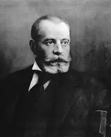
As with the invention of the telephone itself, the honour of "first telephone exchange" has several claimants. One of the first to propose a telephone exchange was Hungarian Tivadar Puskás in 1877 while he was working for Thomas Edison.[4][5][6][7][8] The first experimental telephone exchange was based on the ideas of Puskás, and it was built by the Bell Telephone Company in Boston in 1877.[9] The world's first state-administered telephone exchange opened on November 12, 1877 in Friedrichsberg close to Berlin under the direction of Heinrich von Stephan.[10] George W. Coy designed and built the first commercial US telephone exchange which opened in New Haven, Connecticut in January, 1878. The switchboard was built from "carriage bolts, handles from teapot lids and bustle wire" and could handle two simultaneous conversations.[11] Charles Glidden is also credited with establishing an exchange in Lowell, MA. with 50 subscribers in 1878.
In Europe other early telephone exchanges were based in London and Manchester, both of which opened under Bell patents in 1879.[12] Belgium had its first International Bell exchange (in Antwerp) a year later.
In 1887 Puskás introduced the multiplex switchboard. .[13]
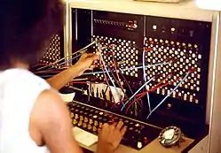
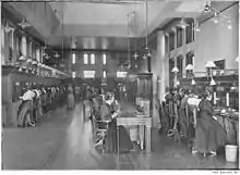
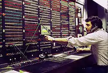
Later exchanges consisted of one to several hundred plug boards staffed by switchboard operators. Each operator sat in front of a vertical panel containing banks of ¼-inch tip-ring-sleeve (3-conductor) jacks, each of which was the local termination of a subscriber's telephone line. In front of the jack panel lay a horizontal panel containing two rows of patch cords, each pair connected to a cord circuit.
When a calling party lifted the receiver, the local loop current lit a signal lamp near the jack.[14] The operator responded by inserting the rear cord (answering cord) into the subscriber's jack and switched her headset into the circuit to ask, "Number, please?" For a local call, the operator inserted the front cord of the pair (ringing cord) into the called party's local jack and started the ringing cycle. For a long-distance call, she plugged into a trunk circuit to connect to another operator in another bank of boards or at a remote central office. In 1918, the average time to complete the connection for a long-distance call was 15 minutes.[14]
Early manual switchboards required the operator to operate listening keys and ringing keys, but by the late 1910s and 1920s, advances in switchboard technology led to features which allowed the call to be automatically answered immediately as the operator inserted the answering cord, and ringing would automatically begin as soon as the operator inserted the ringing cord into the called party's jack. The operator would be disconnected from the circuit, allowing her to handle another call, while the caller heard an audible ringback signal, so that that operator would not have to periodically report that she was continuing to ring the line.[15]
In the ringdown method, the originating operator called another intermediate operator who would call the called subscriber, or passed it on to another intermediate operator.[16] This chain of intermediate operators could complete the call only if intermediate trunk lines were available between all the centers at the same time. In 1943 when military calls had priority, a cross-country US call might take as long as 2 hours to request and schedule in cities that used manual switchboards for toll calls.
On March 10, 1891, Almon Brown Strowger, an undertaker in Kansas City, Missouri, patented the stepping switch, a device which led to the automation of telephone circuit switching. While there were many extensions and adaptations of this initial patent, the one best known consists of 10 levels or banks, each having 10 contacts arranged in a semicircle. When used with a rotary telephone dial, each pair of digits caused the shaft of the central contact "hand" of the stepping switch to first step (ratchet) up one level for each pulse in the first digit and then to swing horizontally in a contact row with one small rotation for each pulse in the next digit.
Later stepping switches were arranged in banks, the first stage of which was a linefinder. If one of up to a hundred subscriber lines (two hundred lines in later linefinders) had the receiver lifted "off hook", a linefinder connected the subscriber's line to a free first selector, which returned the subscriber a dial tone to show that it was ready to receive dialled digits. The subscriber's dial pulsed at about 10 pulses per second, although the speed depended on the standard of the particular telephone administration.
Exchanges based on the Strowger switch were eventually challenged by other exchange types and later by crossbar technology. These exchange designs promised faster switching and would accept inter-switch pulses faster than the Strowger's typical 10 pps—typically about 20 pps. At a later date many also accepted DTMF "touch tones" or other tone signaling systems.
A transitional technology (from pulse to DTMF) had converters to convert DTMF to pulse, to feed to older Strowger, panel, or crossbar switches. This technology was used as late as mid-2002.
Terminology
Many terms used in telecommunication technology differ in meaning and usage among the various English speaking regions. For the purpose of this article the following definitions are made:
- Manual service is telephone service in which a human telephone operator routes calls as instructed by a subscriber with a telephone set that does not have a dial.
- Dial service is when an exchange routes calls by interpreting subscriber-dialed digits.
- A telephone switch is the switching equipment of an exchange.
- A wire center is the area served by a particular switch or central office.
- A concentrator is a device that concentrates traffic, be it remote or co-located with the switch.
- An off-hook condition represents a circuit that is in use, e.g., when a telephone call is in progress.
- An on-hook condition represents an idle circuit, i.e. no telephone call is in progress.
A central office originally was a primary exchange in a city with other exchanges service parts of the area. The term became to mean any switching system including its facilities and operators. It is also used generally for the building that houses switching and related inside plant equipment. In United States telecommunication jargon, a central office (C.O.) is a common carrier switching center Class 5 telephone switch in which trunks and local loops are terminated and switched.[17] In the UK, a telephone exchange means an exchange building, and is also the name for a telephone switch.
Manual service exchanges
With manual service, the customer lifts the receiver off-hook and asks the operator to connect the call to a requested number. Provided that the number is in the same central office, and located on the operator's switchboard, the operator connects the call by plugging the ringing cord into the jack corresponding to the called customer's line. If the called party's line is on a different switchboard in the same office, or in a different central office, the operator plugs into the trunk for the destination switchboard or office and asks the operator answering (known as the "B" operator) to connect the call.
Most urban exchanges provided common-battery service, meaning that the central office provided power to the subscriber telephone circuits for operation of the transmitter, as well as for automatic signaling with rotary dials. In common-battery systems, the pair of wires from a subscriber's telephone to the exchange carry 48V (nominal) DC potential from the telephone company end across the conductors. The telephone presents an open circuit when it is on-hook or idle.[18]
When a subscriber's phone is off-hook, it presents an electrical resistance across the line which causes current to flow through the telephone and wires to the central office. In a manually operated switchboard, this current flowed through a relay coil, and actuated a buzzer or a lamp on the operator's switchboard, signaling the operator to perform service.[18]
In the largest cities, it took many years to convert every office to automatic equipment, such as a panel switch. During this transition period, once numbers were standardized to the 2L-4N or 2L-5N format (two-letter exchange name and either four or five digits), it was possible to dial a number located in a manual exchange and be connected without requesting operator assistance. The policy of the Bell System stated that customers in large cities should not need to be concerned with the type of office, whether they were calling a manual or an automatic office.
When a subscriber dialed the number of a manual station, an operator at the destination office answered the call after seeing the number on an indicator, and connected the call by plugging a cord into the outgoing circuit and ringing the destination station. For example, if a dial customer calling from TAylor 4725 dialed a number served by a manual exchange, e.g., ADams 1383-W, the call was completed, from the subscriber's perspective, exactly as a call to LEnnox 5813, in an automated exchange. The party line letters W, R, J, and M were only used in manual exchanges with jack-per-line party lines.
In contrast to the listing format MAin 1234 for an automated office with two capital letters, a manual office, having listings such as Hillside 834 or East 23, was recognizable by the format in which the second letter was not capitalized.
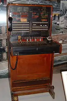
Rural areas, as well as the smallest towns, had manual service and signaling was accomplished with magneto telephones, which had a crank for the signaling generator. To alert the operator, or another subscriber on the same line, the subscriber turned the crank to generate ringing current. The switchboard responded by interrupting the circuit, which dropped a metal tab above the subscriber's line jack and sounded a buzzer. Dry cell batteries, normally two large N°. 6 cells in the subscriber's telephone, provided the direct current for the transmitter. Such magneto systems were in use in the US as late as 1983, as in the small town, Bryant Pond, Woodstock, Maine.
Many small town magneto systems featured party lines, anywhere from two to ten or more subscribers sharing a single line. When calling a party, the operator used code ringing, a distinctive ringing signal sequence, such as two long rings followed by one short ring. Everyone on the line could hear the signals, and could pick up and monitor other people's conversations.
Early automatic exchanges
Automatic exchanges, or dial service, came into existence in the early 20th century. Their purpose was to eliminate the need for human switchboard operators who completed the connections required for a telephone call. Automation replaced human operators with electromechanical systems and telephones were equipped with a dial by which a caller transmitted the destination telephone number to the automatic switching system.
A telephone exchange automatically senses an off-hook condition of the telephone when the user removes the handset from the switchhook or cradle. The exchange provides dial tone at that time to indicate to the user that the exchange is ready to receive dialed digits. The pulses or DTMF tones generated by the telephone are processed and a connection is established to the destination telephone within the same exchange or to another distant exchange.
The exchange maintains the connection until one of the parties hangs up. This monitoring of connection status is called supervision. Additional features, such as billing equipment, may also be incorporated into the exchange.
The Bell System dial service implemented a feature called automatic number identification (ANI) which facilitated services like automated billing, toll-free 800-numbers, and 9-1-1 service. In manual service, the operator knows where a call is originating by the light on the switchboard jack field. Before ANI, long-distance calls were placed into an operator queue and the operator asked the calling party's number and recorded it on a paper toll ticket.
Early exchanges were electromechanical systems using motors, shaft drives, rotating switches and relays. Some types of automatic exchanges were the Strowger switch or step-by-step switch, All Relay, X-Y, panel switch, Rotary system and the crossbar switch.
Electromechanical signaling
Circuits interconnecting switches are called trunks. Before Signalling System 7, Bell System electromechanical switches in the United States originally communicated with one another over trunks using a variety of DC voltages and signaling tones, replaced today by digital signals.
Some signaling communicated dialed digits. An early form called Panel Call Indicator Pulsing used quaternary pulses to set up calls between a panel switch and a manual switchboard. Probably the most common form of communicating dialed digits between electromechanical switches was sending dial pulses, equivalent to a rotary dial's pulsing, but sent over trunk circuits between switches.
In Bell System trunks, it was common to use 20 pulse-per-second between crossbar switches and crossbar tandems. This was twice the rate of Western Electric/Bell System telephone dials. Using the faster pulsing rate made trunk utilization more efficient because the switch spent half as long listening to digits. DTMF was not used for trunk signaling.
Multi-frequency (MF) was the last of the pre-digital methods. It used a different set of tones sent in pairs like DTMF. Dialing was preceded by a special keypulse (KP) signal and followed by a start (ST). Variations of the Bell System MF tone scheme became a CCITT standard. Similar schemes were used in the Americas and in some European countries including Spain. Digit strings between switches were often abbreviated to further improve utilization.
For example, one switch might send only the last four or five digits of a telephone number. In one case, seven digit numbers were preceded by a digit 1 or 2 to differentiate between two area codes or office codes, (a two-digit-per-call savings). This improved revenue per trunk and reduced the number of digit receivers needed in a switch. Every task in electromechanical switches was done in big metallic pieces of hardware. Every fractional second cut off of call set up time meant fewer racks of equipment to handle call traffic.
Examples of signals communicating supervision or call progress include E and M signaling, SF signaling, and robbed-bit signaling. In physical (not carrier) E and M trunk circuits, trunks were four wire. Fifty trunks would require a hundred pair cable between switches, for example. Conductors in one common circuit configuration were named tip, ring, ear (E) and mouth (M). Tip and ring were the voice-carrying pair, and named after the tip and ring on the three conductor cords on the manual operator's console.
In two-way trunks with E and M signaling, a handshake took place to prevent both switches from colliding by dialing calls on the same trunk at the same time. By changing the state of these leads from ground to -48 volts, the switches stepped through a handshake protocol. Using DC voltage changes, the local switch would send a signal to get ready for a call and the remote switch would reply with an acknowledgment (a wink) to go ahead with dial pulsing. This was done with relay logic and discrete electronics.
These voltage changes on the trunk circuit would cause pops or clicks that were audible to the subscriber as the electrical handshaking stepped through its protocol. Another handshake, to start timing for billing purposes, caused a second set of clunks when the called party answered.
A second common form of signaling for supervision was called single-frequency or SF signaling. The most common form of this used a steady 2,600 Hz tone to identify a trunk as idle. Trunk circuitry hearing a 2,600 Hz tone for a certain duration would go idle. (The duration requirement reduced falsing.) Some systems used tone frequencies over 3,000 Hz, particularly on SSB frequency division multiplex microwave radio relays.
On T-carrier digital transmission systems, bits within the T-1 data stream were used to transmit supervision. By careful design, the appropriated bits did not change voice quality appreciably. Robbed bits were translated to changes in contact states (opens and closures) by electronics in the channel bank hardware. This allowed direct current E and M signaling, or dial pulses, to be sent between electromechanical switches over a digital carrier which did not have DC continuity.
Noise
A characteristic of electromechanical switching equipment is that the maintenance staff could hear the mechanical clattering of Strowgers, panel switches or crossbar relays. During heavy use periods, it could be difficult to converse in a central office switch room due to the clatter of calls being processed in a large switch. For example, on Mother's Day in the US, or on a Friday evening around 5pm, the metallic rattling could make raised voices necessary. For wire spring relay markers these noises resembled hail falling on a metallic roof.
On a pre-dawn Sunday morning, call processing might slow to the extent that one might be able to hear individual calls being dialed and set up. There were also noises from whining power inverters and whirring ringing generators. Some systems had a continual, rhythmic "clack-clack-clack" from wire spring relays that made reorder (120 ipm) and busy (60 ipm) signals.
Bell System installations typically had alarm bells, gongs, or chimes to announce alarms calling attention to a failed switch element. A trouble reporting card system was connected to switch common control elements. These trouble reporting systems punctured cardboard cards with a code that logged the nature of a failure. Reed relay technology in stored program control exchange finally quieted the environment.
Maintenance tasks
Electromechanical switching systems required sources of electricity in form of direct current (DC), as well as alternating ring current (AC), which were generated on-site with mechanical generators. In addition, telephone switches required adjustment of many mechanical parts. Unlike modern switches, a circuit connecting a dialed call through an electromechanical switch had DC continuity within the local exchange area via metallic conductors.
The design and maintenance procedures of all systems involved methods to avoid that subscribers experienced undue changes in the quality of the service or that they noticed failures. A variety of tools referred to as make-busys were plugged into electromechanical switch elements upon failure and during repairs. A make-busy identified the part being worked on as in-use, causing the switching logic to route around it. A similar tool was called a TD tool. Delinquent subscribers had their service temporarily denied (TDed). This was effected by plugging a tool into the subscriber's office equipment on Crossbar systems or line group in step-by-step switches. The subscriber could receive calls but could not dial out.
Strowger-based, step-by-step offices in the Bell System required continuous maintenance, such as cleaning. Indicator lights on equipment bays alerted staff to conditions such as blown fuses (usually white lamps) or a permanent signal (stuck off-hook condition, usually green indicators). Step offices were more susceptible to single-point failures than newer technologies.
Crossbar offices used more shared, common control circuits. For example, a digit receiver (part of an element called an Originating Register) would be connected to a call just long enough to collect the subscriber's dialed digits. Crossbar architecture was more flexible than step offices. Later crossbar systems had punch-card-based trouble reporting systems. By the 1970s, automatic number identification had been retrofitted to nearly all step-by-step and crossbar switches in the Bell System.
Electronic switches
Electronic switching systems gradually evolved in stages from electromechanical hybrids with stored program control to the fully digital systems. Early systems used reed relay-switched metallic paths under digital control. Equipment testing, phone numbers reassignments, circuit lockouts and similar tasks were accomplished by data entry on a terminal.
Examples of these systems included the Western Electric 1ESS switch, Northern Telecom SP1, Ericsson AXE, Automatic Electric EAX-1 & EAX-2, Philips PRX/A, ITT Metaconta, British GPO/BT TXE series and several other designs were similar. Ericsson also developed a fully computerized version of their ARF crossbar exchange called ARE. These used a crossbar switching matrix with a fully computerized control system and provided a wide range of advanced services. Local versions were called ARE11 while tandem versions were known as ARE13. They were used in Scandinavia, Australia, Ireland and many other countries in the late 1970s and into the 1980s when they were replaced with digital technology.
These systems could use the old electromechanical signaling methods inherited from crossbar and step-by-step switches. They also introduced a new form of data communications: two 1ESS exchanges could communicate with one another using a data link called Common Channel Interoffice Signaling, (CCIS). This data link was based on CCITT 6, a predecessor to SS7. In European systems R2 signalling was normally used.
Digital switches
First concepts of digital switching and transmission were developed by various labs in the United States and in Europe starting in the 1930s. The first prototype digital switch was developed by Bell Labs as part of the ESSEX project while the first true digital exchange to be combined with digital transmission systems was designed by LCT (Laboratoire Central de Telecommunications) in Paris. The first digital switch to be placed into a public network in England was the Empress Exchange in London which was designed by the General Post Office research labs. It was a tandem switch that connected three Strowger exchanges. The first commercial roll-out of a fully digital local switching system was Alcatel's E10 system which began serving customers in Brittany in Northwestern France in 1972.
Prominent examples of digital switches include:
- Ericsson's AXE telephone exchange is the most widely used digital switching platform in the world and can be found throughout Europe and in most countries around the world. It is also very popular in mobile applications. This highly modular system was developed in Sweden in the 1970s as a replacement for the very popular range of Ericsson crossbar switches ARF, ARM, ARK and ARE used by many European networks from the 1950s onwards.
- Alcatel-Lucent inherited three of the world's most iconic digital switching systems : Alcatel E10, 1000-S12, and the Western Electric 5ESS.
- Alcatel developed the E10 system in France during the late 1960s and 1970s. This widely used family of digital switches was one of the earliest TDM switches to be widely used in public networks. Subscribers were first connected to E10A switches in France in 1972. This system is used in France, Ireland, China, and many other countries. It has been through many revisions and current versions are even integrated into All IP networks.
- Alcatel also acquired ITT System 12 which when it bought ITT's European operations. The S12 system and E10 systems were merged into a single platform in the 1990s. The S12 system is used in Germany, Italy, Australia, Belgium, China, India, and many other countries around the world.
- Finally, when Alcatel and Lucent merged, the company acquired Lucent's 5ESS and 4ESS systems used throughout the United States of America and in many other countries.
- Nokia Siemens Networks EWSD originally developed by Siemens, Bosch and DeTeWe for the German market is used throughout the world.
- Nortel then Genband, and now Ribbon Communications DMS100 and other versions are very popular with operators all over the world.
- GTD-5 EAX developed by GTE Automatic Electric, the GTD-5 was acquired by Lucent which became Alcatel-Lucent, which then became Nokia
- NEC NEAX used in Japan, New Zealand and many other countries.
- Marconi System X originally developed by GPT and Plessey is a type of digital exchange used by BT Group in the UK public telephone network.
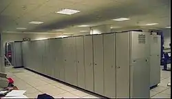
Digital switches encode the speech going on, in 8,000 time slices per second. At each time slice, a digital PCM representation of the tone is made. The digits are then sent to the receiving end of the line, where the reverse process occurs, to produce the sound for the receiving phone. In other words, when someone uses a telephone, the speaker's voice is "encoded" then reconstructed for the person on the other end. The speaker's voice is delayed in the process by a small fraction of one second — it is not "live", it is reconstructed — delayed only minutely.
Individual local loop telephone lines are connected to a remote concentrator. In many cases, the concentrator is co-located in the same building as the switch. The interface between remote concentrators and telephone switches has been standardised by ETSI as the V5 protocol. Concentrators are used because most telephones are idle most of the day, hence the traffic from hundreds or thousands of them may be concentrated into only tens or hundreds of shared connections.
Some telephone switches do not have concentrators directly connected to them, but rather are used to connect calls between other telephone switches. These complex machines are referred to as "carrier-level" switches or tandem switches.
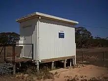
Some telephone exchange buildings in small towns house only remote or satellite switches, and are homed upon a "parent" switch, usually several kilometres away. The remote switch is dependent on the parent switch for routing. Unlike a digital loop carrier, a remote switch can route calls between local phones itself, without using trunks to the parent switch.

The switch's place in the network
Telephone switches are a small component of a large network. A major part, in terms of expense, maintenance, and logistics of the telephone system is outside plant, which is the wiring outside the central office. While many subscribers were served with party-lines in the middle of the 20th century, it was the goal that each subscriber telephone station were connected to an individual pair of wires from the switching system.
A typical central office may have tens of thousands of pairs of wires that appear on terminal blocks called the main distribution frame (MDF). A component of the MDF is protection: fuses or other devices that protect the switch from lightning, shorts with electric power lines, or other foreign voltages. In a typical telephone company, a large database tracks information about each subscriber pair and the status of each jumper. Before computerization of Bell System records in the 1980s, this information was handwritten in pencil in accounting ledger books.
To reduce the expense of outside plant, some companies use "pair gain" devices to provide telephone service to subscribers. These devices are used to provide service where existing copper facilities have been exhausted or by siting in a neighborhood, can reduce the length of copper pairs, enabling digital services such as Integrated Services Digital Network (ISDN) or digital subscriber line (DSL).
Pair gain or digital loop carriers (DLCs) are located outside the central office, usually in a large neighborhood distant from the CO. DLCs are often referred to as Subscriber Loop Carriers (SLCs), after a Lucent proprietary product.
DLCs can be configured as universal (UDLCs) or integrated (IDLCs). Universal DLCs have two terminals, a central office terminal (COT) and a remote terminal (RT), that function similarly. Both terminals interface with analog signals, convert to digital signals, and transport to the other side where the reverse is performed.
Sometimes, the transport is handled by separate equipment. In an Integrated DLC, the COT is eliminated. Instead, the RT is connected digitally to equipment in the telephone switch. This reduces the total amount of equipment required.
Switches are used in both local central offices and in long distance centers. There are two major types in the Public switched telephone network (PSTN), the Class 4 telephone switches designed for toll or switch-to-switch connections, and the Class 5 telephone switches or subscriber switches, which manage connections from subscriber telephones. Since the 1990s, hybrid Class 4/5 switching systems that serve both functions have become common.
Another element of the telephone network is time and timing. Switching, transmission and billing equipment may be slaved to very high accuracy 10 MHz standards which synchronize time events to very close intervals. Time-standards equipment may include Rubidium- or Caesium-based standards and a Global Positioning System receiver.
Switch design
Long-distance switches may use a slower, more efficient switch-allocation algorithm than local central offices, because they have near 100% utilization of their input and output channels. Central offices have more than 90% of their channel capacity unused.
Traditional telephone switches connected physical circuits (e.g., wire pairs) while modern telephone switches use a combination of space- and time-division switching. In other words, each voice channel is represented by a time slot (say 1 or 2) on a physical wire pair (A or B). In order to connect two voice channels (say A1 and B2) together, the telephone switch interchanges the information between A1 and B2. It switches both the time slot and physical connection. To do this, it exchanges data between the time slots and connections 8,000 times per second, under control of digital logic that cycles through electronic lists of the current connections. Using both types of switching makes a modern switch far smaller than either a space or time switch could be by itself.
The structure of a switch is an odd number of layers of smaller, simpler subswitches. Each layer is interconnected by a web of wires that goes from each subswitch, to a set of the next layer of subswitches. In some designs, a physical (space) switching layer alternates with a time switching layer. The layers are symmetric, because in a telephone system callers can also be called. Other designs use time-switching only, throughout the switch.
A time-division subswitch reads a complete cycle of time slots into a memory, and then writes it out in a different order, also under control of a cyclic computer memory. This causes some delay in the signal.
A space-division subswitch switches electrical paths, often using some variant of a nonblocking minimal spanning switch, or a crossover switch.
Switch control algorithms
Fully connected mesh network
One way is to have enough switching fabric to assure that the pairwise allocation will always succeed by building a fully connected mesh network. This is the method usually used in central office switches, which have low utilization of their resources.
Clos's nonblocking switch algorithm
The connections between layers of subswitches of telephone switching system are scarce resources, allocated by special control logic in a fault tolerant manner. Clos networks are often used.
Fault tolerance
Composite switches are inherently fault-tolerant. If a subswitch fails, the controlling computer can sense it during a periodic test. The computer marks all the connections to the subswitch as "in use". This prevents new calls, and does not interrupt old calls that remain working. As calls in progress end, the subswitch becomes unused, and new calls avoid the subswitch because it's already "in use." Some time later, a technician can replace the circuit board. When the next test succeeds, the connections to the repaired subsystem are marked "not in use", and the switch returns to full operation.
To prevent frustration with unsensed failures, all the connections between layers in the switch are allocated using first-in-first-out lists (queues). As a result, if a connection is faulty or noisy and the customer hangs up and redials, they will get a different set of connections and subswitches. A last-in-first-out (stack) allocation of connections might cause a continuing string of very frustrating failures.
Fire and disaster recovery
The central exchange, due to the system's design, is almost always a single point of failure for local calls. As the capacity of individual switches and the optical fibre which interconnects them increases, potential disruption caused by destruction of one local office will only be magnified. Multiple fibre connections can be used to provide redundancy to voice and data connections between switching centres, but careful network design is required to avoid situations where a main fibre and its backup both go through the same damaged central office as a potential common mode failure.[19]
See also
References
- "General Definitions". Verizon service. Verizon Enterprise Solutions.
- Private Telegraphs, The Sydney Morning Herald, credited to The Times, April 19, 1878, p. 6.
- Bo Leuf (2002). Peer to Peer: Collaboration and Sharing Over the Internet. Addison-Wesley. p. 15. ISBN 9780201767322.
- Alvin K. Benson (2010). Inventors and inventions Great lives from history Volume 4 of Great Lives from History: Inventors & Inventions. Salem Press. p. 1298. ISBN 9781587655227.
- "TIVADAR PUSKÁS (1844 - 1893)". 4 February 2011. Archived from the original on 4 February 2011.
- "SZTNH". Mszh.hu. Retrieved 2012-07-01.
- "Puskás, Tivadar". Omikk.bme.hu. Retrieved 2012-07-01.
- "Welcome hunreal.com - BlueHost.com". Hunreal.com. Archived from the original on 2012-03-16. Retrieved 2012-07-01.
- Frank Lewis Dyer: Edison His Life And Inventions. (page: 71)
- "120 Year Telephone anniversary". cdrecord.org. Archived from the original on 6 November 2014.
- National Park Service "first switchboard" page.
- "Early Manchester telephone exchanges" (PDF). mosi.org.uk. Archived from the original (PDF) on 2013-06-05. Retrieved 2013-07-30.
- Francis S. Wagner: Hungarian Contributions to World Civilization - Page 68
- Calvert, J. B. (2003-09-07). "Basic Telephones". Archived from the original on 2003-12-27. Retrieved 2007-09-13.
- "Stromberg-Carlson Telephone Mfg. Co. Resource Page" (PDF). www.strombergcarlsontelephone.com. Retrieved 2020-09-09.
- Calvert, J. B. (2003-09-07). "Basic Telephones, The Switchboard (ringdown is near bottom)". Archived from the original on 2003-12-27. Retrieved 2006-09-13.
- Source: from Federal Standard 1037C.
- Connected to a switch, an off-hook condition operates a relay to connect the line to a dial tone generator and a device to collect dialed digits.
- Andrew Pollack (1988-05-26). "Phone System Feared Vulnerable To Wider Disruptions of Service" (PDF). New York Times. Retrieved 2013-07-30.
External links
| Wikimedia Commons has media related to Telephone exchanges. |
- Telephone Central Office History and Pictures
- Telephone World's Central Office Building Pictures
- Clive Feather's guide to the BT network
- Roger W. Haworth's guide to London (UK) Director Exchange Names
- patent 252,576 for the first telephone switchboard in 1881
- A Telecom Exchange Tour in NZ