Electrification of the New York, New Haven, and Hartford Railroad
The New York, New Haven and Hartford Railroad pioneered electrification of main line railroads using high-voltage, alternating current, single-phase overhead catenary. It electrified its mainline between Stamford, Connecticut, and Woodlawn, New York, in 1907, and extended the electrification to New Haven, Connecticut, in 1914. While single-phase AC railroad electrification has become commonplace, the New Haven's system was unprecedented at the time of construction. The significance of this electrification was recognized in 1982 by its designation as a National Historic Engineering Landmark by the American Society of Mechanical Engineers (ASME).
Initial Electrification Experiments
The New Haven tried several experiments with low-voltage DC electrification in the decade preceding their main line overhead electrification. These included:
- 1895 electrification of 6.8 mi (11 km) of line between Nantasket Junction and Pemberton, Massachusetts using overhead copper contact wire at 600-700 Vdc.
- This line was extended an additional 3.4 mi (5.5 km) to East Weymouth around 1896.
- Third-rail electrification between Hartford, New Britain, and Berlin, a total of 12 mi (20 km) in 1896. This third-rail system was unique; it consisted of an inverted V (angle) cross-section rail, mounted on the cross ties between the running rails, and was totally exposed.
The third rail system resulted, not surprisingly, in a number of accidents. It also resulted in a decree from the Connecticut Supreme Court on June 13, 1906 forbidding the use of third rail electrification within the state.[1] The New Haven was forced by this decision to design their main line electrification system using overhead catenary.
Several different systems combinations of voltage and frequency were considered in the initial design. Due to the relatively large distances involved, transmission at high voltages using alternate current was recognized as being unavoidable. An architecture similar to commercial DC utilities and urban railroads was considered using high voltage transmission lines, rotary converters, and overhead DC catenary. The studies of the time assumed an electrical efficiency of only 75 percent for this architecture.
The highest voltage for which generators could be reliably designed at this time was about 22 kV. An intermediate design was considered using 22 kV transmission lines, substations to reduce catenary voltage to between 3 and 6 kV, and transformers on the engines to the 560 V required by the traction motors.[1] The railroad realized that it could save significant capital cost if the intermediate substitution were omitted and locomotives received line voltage at around 11 kV.
Original 1907 direct-feed architecture
The New Haven's electrification was the first of its kind; no previous railroad had practical experience operating a high voltage distribution system above a steam railroad. Many of the system's ultimate specifications were the result of educated design decisions based on the state of the electrical technology in 1907.
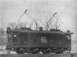
Proposals were obtained from General Electric (GE) and Westinghouse. Both companies submitted a variety of AC and DC schemes, though GE favoured DC electrification. But New Haven chose single-phase AC at 11 kV, 25 Hz. as proposed by Westinghouse, who had been researching AC electrification of railroads since 1895 and in association with Baldwin supplied Baldwin-Westinghouse locomotives.[2] Later GE also supplied some locomotives.
Voltage
The designers considered several voltages for the transmission segment of the system including 3-6 kV, 11 kV, and 22 kV. Ultimately, the transmission and catenary systems were combined into a transformerless system, that utilized the same voltage from output of generator to catenary to locomotive pantograph. As 11 kV was the highest voltage that could be obtained directly from the output of the generators of 1907, 11 kV was selected as the transmission and catenary voltage of the system.
Frequency
The New Haven considered two different operating frequencies for use in their electrification: 15 Hz and 25 Hz. The lower frequency of 15 Hz afforded reduced motor size, lower inductive losses, and a higher motor power factor. 25 Hz had by 1907 already become a commercial standard, and the railroad already operated a number of trolley power houses at 25 Hz and had equipped many of its shops with 25 Hz motors. Selection of 15 Hz viewed by the railroad as a 'break in gage' which would have limited the commercial value of the system. Thus the railroad selected the 25 Hz standard, even though it might have been more desirable from an engineering perspective. Note that many European railroads standardized on a 16.7 Hz traction power frequency.
Catenary
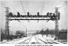
The New Haven had no precedent to follow when designing its catenary system. Overhead catenary had previously been the domain of trolleys, except for a few three-phase railways in Europe. No prior experience existed with operating high-speed railways with an overhead contact system. The catenary designed by the New Haven was a unique, relatively rigid triangular cross-section.
The triangular cross-section of catenary used in the original electrification was only repeated by one other railway. The London, Brighton and South Coast Railway used a similar triangular catenary from 1909 until 1929.[3] The New Haven's 1914 extensions dispensed with the triangular catenary design.
Catenary support spacing was set at 300 feet (91 m). This was based on keeping the straight line deviation from center of track to within 8.5 inches (220 mm) with a curve radius of 3 degree, which was the tightest curve between the original system's termini at Woodlawn and Stamford.
Generators
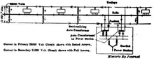
The generators at the Cos Cob Power Station were designed to supply single-phase power directly to the catenary. They were also required to supply three-phase power both to the New Haven itself for use along the lines,[4] and to the New York Central's (NYC) Port Morris generating station to compensate the NYC for the power consumed by New Haven trains on the NYC's third-rail supplied line to Grand Central Terminal.[1] The Cos Cob generators were three-phase machines, but wired to supply both three phase and single phase power simultaneously.
Revised 1914 autotransformer architecture
Although the railroad considered the 1907 electrification highly successful, two problems required an ultimate redesign of the transmission system. The first was electromagnetic interference in adjacent, parallel telegraph and telephone wires caused by the high currents in the traction power system.
The second was that the system's geographic growth and the evolving state of electrical technology created a need for higher transmission voltages. The railroad could have simply raised the operating voltage of the entire system, however this would have required all the catenary insulators to be upgraded to withstand a higher potential, and replacement of all the locomotive high voltage equipment. And while higher transmission voltages had become common in the seven years since the initial electrification, generators were still limited by economics to a maximum output voltage of around 11 kV.
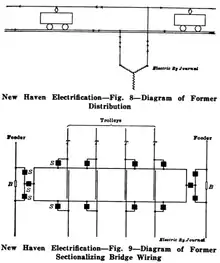
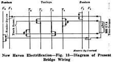
The solution decided upon by the railroad, after several years of study, was a balanced autotransformer system.
Remarkably, the railroad changed transmission system architectures within four hours, although preliminary work had taken the preceding 18 months. On Sunday, January 25, 1914, the railroad shut down the entire power system at 2 am. Gangs of workers throughout the system reconfigured the transmission lines over the next 70 minutes. System startup was commenced and by 5:30 am, electric trains were running over the new, autotransformer supplied system.[5]
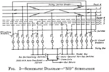
Substations
| Substation No. | Catenary Bridge No. | Name | Built | Coordinates | Comments |
|---|---|---|---|---|---|
| New Haven Line | |||||
| 1114 | Cedar Hill | ||||
| 1104 | Mill River (Section Break) | ||||
| 1060 | Cedar St. | 41.2937°N 72.9305°W | |||
| 962 | Woodmont | ||||
| 863 | Devon | ||||
| 814 | Bishop Ave | ||||
| 736 | Burr Road | ||||
| 633 | Green's Farms | ||||
| 524 | South Norwalk | ||||
| 465 | Darien | 41.0773°N 73.4686°W | |||
| 374 | Stamford | ||||
| 296 | Greenwich | ||||
| 245 | Port Chester | 41.0053°N 73.6559°W | |||
| 193 | Rye | ||||
| 126 | Mamaroneck | 40.9467°N 73.7446°W | |||
| SS22 | 72 | New Rochelle | 1914 | 40.9127°N 73.7826°W | Converted to 60 Hz c. 1986 |
| 0 | Woodlawn | ||||
| Harlem River and Port Chester Branch | |||||
| ATK 47 | 211H | Amtrak New Rochelle | 1987 | 40.9069°N 73.7900°W | |
| SS14 | 149H | Baychester/Pelham Bridge | 1914–1987 | ||
| SS12 | 139H | Westchester/Pelham Parallel | 1914–1987 | 40.8167°N 73.8933°W | |
| ATK 46 | Amtrak Van Nest | 1987 | 40.8420°N 73.8633°W | ||
| SS8 | 84H | West Farms Junction | 1914-1987. | 40.8347°N 73.8794°W | Supplied from Sherman Creek; later from Con Ed Hell Gate GS.[7] The substation and adjacent passenger station have been demolished; an impound lot occupies the site. |
| SS4 | 58H | Oak Point | 1914–1987 | 40.8075°N 73.9049°W | |
| SS3 | 42H | Bungay St | 1914?-1987 | NH 3ph power supplied to NYC's Port Morris GS[8] to compensate for NH's consumption on NYC DC lines. | |
| SS1 | 2H | Harlem River | 1914-19?? | ||
| New York, Westchester and Boston Railway | |||||
| Columbus Ave Mt Vernon | |||||
| White Plains | |||||
| New York Connecting Railroad | |||||
| ATK 45 | C68 | Bowery Bay | 1918 | 40.7643°N 73.9054°W | |
| Long Island Rail Road Bay Ridge Branch | |||||
| 55 | Fresh Pond | 1927-19?? | |||
| 2 East New York (FC) | 1927-19?? | Connects the single phase to/from PT&T/LIRR's 3 phase 25 Hz. | |||
| 54 | East New York Swg. | 1927-19?? | |||
| 53 | New Lots Ave | 1927-19?? | |||
| 52 | Manhattan Beach | 1927-19?? | |||
| 51 | 4th Ave Bay Ridge | 1927-19?? | |||
Hell Gate Line
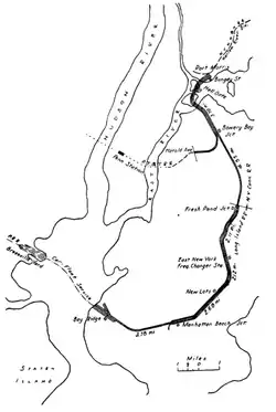
The New Haven's system was extended across the Hell Gate Bridge to the New York Connecting Railroad upon the line's construction. The system of electrification was an extension of the New Haven's revised 11/22 kV autotransformer architecture. The original electrification extended from the New Haven's main line, across the Hell Gate Bridge, to the Bay Ridge yard. The line south of Bowery Bay Junction was de-electrified in the 1950s. The line between New Rochelle and the Harold Interlocking was transferred to Amtrak in 1976 upon dissolution of Penn Central. The electrification system continued to be controlled as a portion of the ex-New Haven system until the 1987 conversion to 60 Hz operation.
When the New Haven main line was converted by Metro-North to 60 Hz operation, the Amtrak Hell Gate line was also converted, but as an isolated system powered from the Van Nest substation. Control of the catenary system was transferred from Cos Cob to the Load Dispatcher at New York Penn Station. Although conversion occurred subsequent to the PRR-era electrification, Amtrak substation numbers 45-47 were assigned for consistency with the rest of the PRR numbering scheme.
See also
- Amtrak's 25 Hz Traction Power System Built by PRR about two decades after New Haven's
- Amtrak's 60 Hz Traction Power System Amtrak's system east of New Haven.
- Baldwin-Westinghouse electric locomotives
- Metro-North Railroad Inherited the system in 1983 from Conrail, which in turn had received it in 1976 from the bankrupt Penn Central.
- Overhead lines
- Railroad electrification in the United States
- Railway electrification system
- SEPTA's 25 Hz Traction Power System Another 1930s era electrification
Footnotes
- McHenry (1907).
- William D. Middleton (1974). When the steam railroads electrified. p. 76. ISBN 0-89024-028-0.
- Savchak (1990).
- Westinghouse figure 19 shows three-phase substations at South Norwalk, Stamford, Greenwich, Port Chester, Van Nest Shops, and Oak Point Float Bridge
- Arthur (1914).
- based on Fig. 21 from Westinghouse Publication 1968.
- The Hell Gate Generating Station was located here: 40.7987°N 73.9095°W
- The New York Central's Port Morris Generating Station was located here: 40.8048°N 73.9021°W
References
Ordered by date of publication.
Early Experiments with Electrical Traction
- Heft, N.H. (June 1897). "Electric Railroading on the New York, New Haven & Hartford System". Street Railway Journal. 13 (6): 329–339. Retrieved July 13, 2011.
- Burch, Edward P. (1911). Electric Traction for Railway Trains. New York: McGraw-Hill Book Company. p. 27. Retrieved July 13, 2011.
1907 Electrification
- Lamme, B.G. (March 1906). "Alternating Current Electric Systems for Heavy Railway Service". Railway Age. 41: 583–590. Retrieved February 15, 2011.
- McHenry, E.H (August 1907). "Electrification of the New York, New Haven and Hartford". The Railroad Gazette. 43: 177–184. Retrieved December 15, 2011.CS1 maint: ref=harv (link). Discussed decisions made during design process, catenary construction.
1914 Autotransformer Upgrade
- "New York, New Haven & Hartford Railroad Electrification," Westinghouse Electric & Manufacturing Company Special Publication 1698, June 1914. Two drawings are available here.
- Arthur, W. (1914). "New Haven Improves Method of Electric Operation". Railway Age Gazette. 56: 988–989. Retrieved February 15, 2011.CS1 maint: ref=harv (link)
- "Reduction of Inductive Interference from the Power Lines of the New Haven Railroad". Electric Railway Journal. 43 (18): 960–966. May 2, 1914. Retrieved February 15, 2011.
- "Minimizing Induction from Single-Phase Railway". Electrical World. 63 (18): 984–986. May 2, 1914. Retrieved April 7, 2011.
- Austin, Edwin (1915). Single-phase Electrical Railways. New York: D. Van Nostrand. pp. 252–269. Retrieved February 16, 2011.
- "Purchased Power for the New Haven". Electric Railway Journal. 46 (25): 1200–1204. December 18, 1915. Retrieved December 14, 2011.
- "Feeding Heavy Single-Phase Load from Three-Phase Units". Electrical World. 66 (24): 1300–1302. 1915. Retrieved February 14, 2011.. Primarily focused on turbine generator details at Sherman Creek Generating Station.
- "West Farms Substation of New Haven Railroad". Electrical World. 66 (24): 1365–1367. 1915. Retrieved February 14, 2011.. Includes a schematic of generator, transformer, and interconnection arrangement.
- Torchio, P. (1916). "Supply of Single-Phase Loads from Central Stations". Transactions of the American Institute of Electrical Engineers. 35 (2): 1293–1313. doi:10.1109/T-AIEE.1916.4765431. ISSN 0096-3860.CS1 maint: ref=harv (link) Discussion of New Haven Substation at West Farms supplied from commercial utility power stations.
Later Articles
- Morton, R.B. (October 1928). "Arrangements of Feeders and Equipment for Electrified Railways". Transactions of the American Institute of Electrical Engineers. 47 (4): 1297–1301. doi:10.1109/T-AIEE.1928.5055139. ISSN 0096-3860.Discusses both original and 1930s vintage PRR electrification systems along with NY Connecting RR system.
- Savchak, M.W. (April 1990). New Haven line catenary replacement. Technical Papers Presented at the 1990 ASME/IEEE Joint Railroad Conference. pp. 91–94. doi:10.1109/RRCON.1990.171665.CS1 maint: ref=harv (link) Discusses some details of the unique New Haven catenary design and constraints upon its replacement caused by the catenary bridge spacing.
- Friedlander, Gordon D. (July 1968). "Railroad electrification: past, present, and future History of systems in the United States". IEEE Spectrum. 5 (7): 50–65. doi:10.1109/MSPEC.1968.5214536. ISSN 0018-9235.
- "Alternating-Current Electrification of the New York, New Haven & Hartford Railroad 1907 - A National Historic Engineering Landmark" (PDF). American Society of Mechanical Engineers and the Institute of Electrical and Electronics Engineers. 1982. Archived from the original (PDF) on 2007-08-03. Retrieved April 28, 2011.
- Middleton, William D. (1974). When the steam railroads electrified. pp. 76–80. ISBN 0-8902-4028-0.