Mipmap
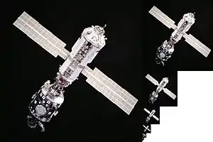
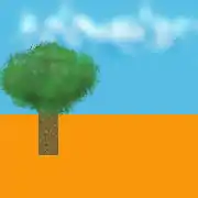
In computer graphics, mipmaps (also MIP maps) or pyramids[1][2][3] are pre-calculated, optimized sequences of images, each of which is a progressively lower resolution representation of the previous. The height and width of each image, or level, in the mipmap is a power of two smaller than the previous level. Mipmaps do not have to be square. They are intended to increase rendering speed and reduce aliasing artifacts. A high-resolution mipmap image is used for high-density samples, such as for objects close to the camera; lower-resolution images are used as the object appears farther away. This is a more efficient way of downfiltering (minifying) a texture than sampling all texels in the original texture that would contribute to a screen pixel; it is faster to take a constant number of samples from the appropriately downfiltered textures. Mipmaps are widely used in 3D computer games, flight simulators, other 3D imaging systems for texture filtering and 2D as well as 3D GIS software. Their use is known as mipmapping. The letters MIP in the name are an acronym of the Latin phrase multum in parvo, meaning "much in little".[4]
Since mipmaps, by definition, are pre-allocated, additional storage space is required to take advantage of them. They are also related to wavelet compression. Mipmap textures are used in 3D scenes to decrease the time required to render a scene. They also improve image quality by reducing aliasing and Moiré patterns that occur at large viewing distances,[5] at the cost of 33% more memory per texture.
Overview

Mipmaps are used for:
- Level of detail (LOD)[6][7]
- Improving image quality. Rendering from large textures where only small, discontiguous subsets of texels are used can easily produce moiré patterns;
- Speeding up rendering times, either by reducing the number of texels sampled to render each pixel, or increasing the memory locality of the samples taken;
- Reducing stress on the GPU or CPU.
Origin
Mipmapping was invented by Lance Williams in 1983 and is described in his paper Pyramidal parametrics.[4] From the abstract: "This paper advances a 'pyramidal parametric' prefiltering and sampling geometry which minimizes aliasing effects and assures continuity within and between target images." The referenced pyramid can be imagined as the set of mipmaps stacked in front of each other.
The origin of the term mipmap is an initialism of the Latin phrase multum in parvo ("much in a small space"), and map, modeled on bitmap.[4] The term pyramids is still commonly used in a GIS context. In GIS software, pyramids are primarily used for speeding up rendering times.
Mechanism

Each bitmap image of the mipmap set is a downsized duplicate of the main texture, but at a certain reduced level of detail. Although the main texture would still be used when the view is sufficient to render it in full detail, the renderer will switch to a suitable mipmap image (or in fact, interpolate between the two nearest, if trilinear filtering is activated) when the texture is viewed from a distance or at a small size. Rendering speed increases since the number of texture pixels (texels) being processed per display pixel can be much lower for similar results with the simpler mipmap textures. If using a limited number of texture samples per display pixel (as is the case with bilinear filtering) then artifacts are reduced since the mipmap images are effectively already anti-aliased. Scaling down and up is made more efficient with mipmaps as well.
If the texture has a basic size of 256 by 256 pixels, then the associated mipmap set may contain a series of 8 images, each one-fourth the total area of the previous one: 128×128 pixels, 64×64, 32×32, 16×16, 8×8, 4×4, 2×2, 1×1 (a single pixel). If, for example, a scene is rendering this texture in a space of 40×40 pixels, then either a scaled-up version of the 32×32 (without trilinear interpolation) or an interpolation of the 64×64 and the 32×32 mipmaps (with trilinear interpolation) would be used. The simplest way to generate these textures is by successive averaging; however, more sophisticated algorithms (perhaps based on signal processing and Fourier transforms) can also be used.


The increase in storage space required for all of these mipmaps is a third of the original texture, because the sum of the areas 1/4 + 1/16 + 1/64 + 1/256 + ⋯ converges to 1/3. In the case of an RGB image with three channels stored as separate planes, the total mipmap can be visualized as fitting neatly into a square area twice as large as the dimensions of the original image on each side (twice as large on each side is four times the original area - one plane of the original size for each of red, green and blue makes three times the original area, and then since the smaller textures take 1/3 of the original, 1/3 of three is one, so they will take the same total space as just one of the original red, green, or blue planes). This is the inspiration for the tag multum in parvo.
Anisotropic filtering
When a texture is viewed at a steep angle, the filtering should not be uniform in each direction (it should be anisotropic rather than isotropic), and a compromise resolution is required. If a higher resolution is used, the cache coherence goes down, and the aliasing is increased in one direction, but the image tends to be clearer. If a lower resolution is used, the cache coherence is improved, but the image is overly blurry. This would be a tradeoff of MIP level of detail (LOD) for aliasing vs blurriness. However anisotropic filtering attempts to resolve this trade-off by sampling a non isotropic texture footprint for each pixel rather than merely adjusting the MIP LOD. This non isotropic texture sampling requires either a more sophisticated storage scheme or a summation of more texture fetches at higher frequencies.[8]
Summed-area tables
Summed-area tables can conserve memory and provide more resolutions. However, they again hurt cache coherence, and need wider types to store the partial sums, which are larger than the base texture's word size. Thus, modern graphics hardware does not support them.
See also
- Spatial anti-aliasing
- Anisotropic filtering
- Pyramid (image processing)
- Hierarchical modulation – similar technique in broadcasting
- Scale space
References
- "Texture Filtering with Mipmaps (Direct3D 9)". microsoft.com. Microsoft.
- "Texture Filtering with Mipmaps". microsoft.com. Microsoft. April 8, 2010.
- "Mipmap Texturing" (PDF). Retrieved December 10, 2019.
- Williams, Lance. "Pyramidal Parametrics" (PDF). Archived from the original (PDF) on 2014-04-14. Retrieved 2012-09-25.
- "Anti-Aliasing Problem and Mipmapping". textureingraphics. 2011-12-13. Retrieved 2019-02-21.
- "Multiple levels of Detail" (PDF).
- "D3D11_SAMPLER_DESC structure". microsoft.com. Microsoft.
- Olano, Marc; Mukherjee, Shrijeet; Dorbie, Angus. "Vertex-based Anisotropic Texturing" (PDF).