Multi-system (rail)
A multi-system locomotive, also known as a multi-system electric locomotive, multi-system electric multiple unit, or multi-system train, is an electric locomotive which can operate using more than one railway electrification system. Multi-system trains provide continuous journeys over routes which are electrified using more than one system.

Reasons
A multi-system locomotive is useful for providing a single journey over multiple electrification systems without interruption, either from requiring passengers to change trains or from changing locomotives. Such conditions can occur where a train crosses national boundaries and each country has implemented a different electrification system.[1]
Examples
European Union
Prior to 1945 there was no demand for multi-system locomotives in Europe. From the 1950s onwards, the emerging formation of the European Union, and the consequent increase in the amount of cross border traffic, along with the addition of a 25 kV 50 Hz AC system in France in addition to the older 1.5 kV DC system, gave rise to the need for multi-voltage locomotives.[2] Very high capital costs prevent or hinder the adoption of a standard railway electrification system.[3]
At the beginning of the 21st century, railway legislation in Europe (the First Railway Package and Second Railway Package, and the creation of a Trans European Rail Freight Network) liberalised cross border freight traffic, giving rise to a demand for locomotives that could work between European Union countries with different electrification systems. That created a practically new market for multi-voltage locomotives, such as Bombardier's TRAXX.[4] However, the increase in the cost of locomotives and maintenance, along with the expense of installing different safety systems for cross-border work, reduced the economic viability of multi-system vehicles versus the use of single-voltage machines or changing locomotives where electrical systems change.[5]
South Africa
South Africa has 15 km of dual system track, both 3 kV DC and 25 kV AC.
United Kingdom

Electrification in the UK began in a piecemeal fashion. The earliest main line (as opposed to metro and tramway) systems were divided between low voltage third rail (commonly about 600 V DC) and overhead systems (a variety of voltages, both DC and AC were used). The third rail systems of this period eventually gave rise to the 750 V DC system in the southern part of the UK and a separate area with the same system around Merseyside.
Cheap loans to stimulate economic development in the 1930s gave rise to the several schemes of 1500 V DC electrification, mostly completed post war, notably between Liverpool Street and Shenfield, and the Woodhead Line. Starting with the West Coast Main Line electrification in the 1960s, the 25 kV AC overhead system was adopted for all subsequent mainline electrification in the UK (except for extensions to other existing systems, mostly on the southern third rail network).
In some areas with restricted clearances, particularly in urban areas in east London (converted from 1500 V DC) and on suburban routes around Glasgow, 6.25 kV was used. A system known as "Automatic Power Control" was developed to allow trains to automatically switch between the voltages whilst moving. All the driver had to do was shut off power and coast until clear of the neutral section; the system automatically opened the circuit breaker, detected a change in voltage and switched over the transformer to the correct input voltage setting, then closed the circuit breaker. This system proved somewhat unreliable and, with experience, it was found that less clearance was needed for 25 kV than had initially been allowed for. This allowed the 6.25 kV sections to be converted to 25 kV, with the last section, at the London end of the London Tilbury and Southend line, being converted in 1983.
United States

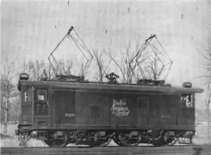
In the United States private companies undertook electrification independently, resulting in divergent systems. Thus the New Haven EP-1 had to support three separate electrification systems: 660 V DC via third rail, 660 V via pantograph, and 11 kV 25 Hz AC via pantograph; in order to make a 27-mile (43 km) journey from the New York Central Railroad's Grand Central Terminal in New York City to its own station in Stamford, Connecticut.[6]
Multi-system operation continues to present day. New Jersey Transit uses multi-system ALP-46 and ALP-45DP locomotives (and also future Multilevel III Electric Multiple-Units) for its Midtown Direct service into New York and Amtrak uses multi-system AEM-7, ACS-64 and Acela locomotives on the Northeast Corridor between Washington DC and Boston. In both cases, through trains run on both newer, 25 kV 60 Hz built or refurbished by their respective agencies since the 1980s and older, 12 kV 25 Hz inherited from the now-defunct Pennsylvania Railroad. The latter dates to the 1930s, when the Pennsylvania upgraded its electrified network from 650 V DC third rail.
See also
References
- "Traxx locomotive family meets European needs". Railway Gazette International. 2008-01-07. Retrieved 2011-01-01.
Traxx MS (multi-system) for operation on both AC (15 and 25 kV) and DC (1.5 and 3 kV) networks
- Andreas Steimel (2007). "8. Multi-system traction vehicles". Electric Traction - Motion Power and Energy Supply. Oldenbourg Industrieverlag. p. 129.
- Hans-Jörg Bullinger (2009). "7. Mobility and Transport". Technology Guide: Principles, Applications, Trends. Springer. p. 295.
- Robert Wright (22 September 2008). "Multi-system: Competition improved by crossborder locomotives". www.ft.com. Financial Times.
- Pamela Luică (26 April 2011). "Multi-system locomotives, still too expensive for operators". www.railwaypro.com. Railway Pro.
- Middleton, William D. (2001) [1974]. When the Steam Railroads Electrified (2nd ed.). Bloomington, Indiana: Indiana University Press. pp. 77–79. ISBN 978-0-253-33979-9.
External links
- M. M. Bakran, H.-G. Eckel, P. Eckert, H. Gambach, U. Wenkemann (Siemens AG) (20–25 June 2004). "Comparison of Multi-System Traction Converters for High-Power Locomotives" (PDF). Power Electronics Specialists Conference, 2004. PESC 04. 2004 IEEE 35th Annual. 1: 697–703. doi:10.1109/PESC.2004.1355833. ISBN 0-7803-8399-0. ISSN 0275-9306. Archived from the original (PDF) on 26 March 2012. Retrieved 23 June 2011.CS1 maint: multiple names: authors list (link)
