Phase distortion synthesis
Phase distortion (PD) synthesis is a synthesis method introduced in 1984 by Casio in its CZ range of synthesizers. In outline, it is similar to phase modulation synthesis as championed by Yamaha Corporation (under the name of frequency modulation), in the sense that both methods dynamically change the harmonic content of a carrier waveform by influence of another waveform (modulator) in the time domain. However, the application and results of the two methods are quite distinct.
Casio made five different synthesizers using their original concept of PD synthesis (with variations). The later VZ-1 and co's synthesis method Interactive phase distortion is much more similar to the aforementioned phase modulation, rather than a direct evolution of phase distortion; see below.
Generating harmonic content
Casio's implementation of PD used oscillators generated by modulator and carrier waveforms, synchronised to each other per-cycle. The modulators were various angular waves that could 'distort' the carrier's sine into other shapes, to a degree derived from the "DCW" envelope. In doing so, many harmonics were created in the output. As modulators were rich in harmonic content, they could create spectra more linear, i.e. more similar to traditional subtractive spectra, than Yamaha's phase modulation (PM/FM) synthesis. PM does not require oscillator sync but was for a long time limited to sine waves, which meant output spectra bore the non-linear hallmark of Bessel functions. PD is a different type of PM - whose very different modulators caused significant difference in operation and sound between PD and PM. Thus the two aren't directly equivalent.
The phase transforms are all assembled from piecewise linear functions under binary logic control and shows characteristic sharp knees (and for some transforms, even sudden jumps) as they move from minimum to maximum, where the frequency counter's accumulator wraps around and starts over. The sharp knees are smoothed by the roundness of the modulated sine wave and not too noticeable in the resulting signal.
Simulating a resonant filter
As well as being more capable of generating traditional linear spectra, the CZ synthesizers can also emulate resonant filter sweeps. This was done using sine waves at the resonant frequency, synchronised and windowed at the fundamental frequency. Frequencies could be controlled but not resonance amount.

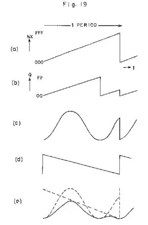
Figure 19 from the 1985 CZ-series patent shows how to emulate the variable resonance found in analogue voltage-controlled filters:
- (a) The base frequency counter, wrapping around every period.
- (b) The resonance frequency counter at a slightly higher frequency, being reset (or "synced") when the base counter wraps around.
- (c) The resonance frequency counter used as a sine wave readout. Note the sudden jump at the reset, which causes significant distortion.
- (d) The inverted base frequency counter.
- (e) Multiplying c by d. The sudden jump in c is now leveled out.
To summarize in other terms: The resonance is a form of digital hard sync, composed of a sine wave at the resonant frequency, amplitude enveloped by and hard-synced to a window function at the fundamental frequency. The window function can take various shapes, including sawtooth and triangle, thus determining the 'basal' spectrum upon which the resonant effect is superimposed. Since the amplitude of all available window functions ends at zero, this removes sharp discontinuities in the synced sine wave, which is a well-known way to reduce aliasing in digital sync. However, some aliasing is still present due to discontinuities in the function's derivatives. Thus, filter sweep effects are generated the same way as sync effects: by modulating the frequency of the resonance (DCW envelope), the timbre changes, adding and subtracting harmonics to/from the chosen fundamental spectrum around the chosen resonant frequency.
Comparison to other types of synthesis
As outlined above, phase distortion broadly applies similar mathematical concepts to phase modulation synthesis, but their implementation and results are not equivalent. Whereas PM - pioneered by John Chowning and commercially used by Yamaha - uses an oscillating modulator that can have its own period, PD applies an angular modulator of straight-line segments hard-synchronised to the same period as its corresponding carrier, i.e. modulating each cycle identically. PM/FM produces Bessel function-derived spectra unless linearised by the application of feedback, whereas PD produces more linear spectra. This manifests in PD synths' reputation for being easier to produce traditional subtractive sounds, such as those typically associated with analogue synths, which are characterised by linear spectra. These facts demonstrate how although the broad concept - alteration of phase - is the same, implementation and results differ greatly.
Casio's own later engine named Interactive Phase Distortion (iPD), which featured in their VZ synths (VZ-1, VZ-10M, and VZ-8M; the first two also rebadged by Hohner as the HS-2 resp. HS-2/E), actually bears very little resemblance to 'actual' PD, being based around an idiosyncratic type of PM instead. In iPD, multiple oscillators are combined in various configurable routings (similar to Yamaha's "algorithms") and can modulate each other using PM or ring modulation (the latter not available in Yamaha's system). However, unlike in Yamaha's implementations, direct PM is restricted to a carrier:modulator ratio of 0:1 (the carrier's frequency is forced to zero, essentially turning it into a simple waveshaper) - with other ratios requiring workarounds and often making some oscillators contribute little or nothing to the desired sound. iPD has some added features that give it advantages in some contexts, but it is generally not as versatile as Yamaha's method for 'pure' phase modulation.