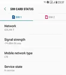
Received signal strength indication
In telecommunications, received signal strength indicator (RSSI) is a measurement of the power present in a received radio signal.[1]

RSSI is usually invisible to a user of a receiving device. However, because signal strength can vary greatly and affect functionality in wireless networking, IEEE 802.11 devices often make the measurement available to users.
RSSI is often derived in the intermediate frequency (IF) stage before the IF amplifier. In zero-IF systems, it is derived in the baseband signal chain, before the baseband amplifier. RSSI output is often a DC analog level. It can also be sampled by an internal analog-to-digital converter (ADC) and the resulting codes available directly or via peripheral or internal processor bus.
In 802.11 implementations
In an IEEE 802.11 system, RSSI is the relative received signal strength in a wireless environment, in arbitrary units. RSSI is an indication of the power level being received by the receiving radio after the antenna and possible cable loss. Therefore, the greater the RSSI value, the stronger the signal. Thus, when an RSSI value is represented in a negative form (e.g. −100), the closer the value is to 0, the stronger the received signal has been.
RSSI can be used internally in a wireless networking card to determine when the amount of radio energy in the channel is below a certain threshold at which point the network card is clear to send (CTS). Once the card is clear to send, a packet of information can be sent. The end-user will likely observe an RSSI value when measuring the signal strength of a wireless network through the use of a wireless network monitoring tool like Wireshark, Kismet or Inssider. As an example, Cisco Systems cards have an RSSI maximum value of 100 and will report 101 different power levels, where the RSSI value is 0 to 100. Another popular Wi-Fi chipset is made by Atheros. An Atheros-based card will return an RSSI value of 0 to 127 (0x7f) with 128 (0x80) indicating an invalid value.
There is no standardized relationship of any particular physical parameter to the RSSI reading. The 802.11 standard does not define any relationship between RSSI value and power level in milliwatts or decibels referenced to one milliwatt (dBm). Vendors and chipset makers provide their own accuracy, granularity, and range for the actual power (measured as milliwatts or decibels) and their range of RSSI values (from 0 to RSSI maximum).[2] One subtlety of the 802.11 RSSI metric comes from how it is sampled—RSSI is acquired during only the preamble stage of receiving an 802.11 frame, not over the full frame.[3]
As early as 2000, researchers were able to use RSSI for coarse-grained location estimates.[4] More recent work was able to reproduce these results using more advanced techniques.[5] Nevertheless, RSSI does not always provide measurements that are sufficiently accurate to properly determine the location.[6] However, RSSI still represents the most feasible indicator for localization purposes as it is available in almost all wireless nodes and it does not need any additional hardware requirements.[7]
Received channel power indicator
For the most part, 802.11 RSSI has been replaced with received channel power indicator (RCPI). RCPI is an 802.11[3] measure of the received radio frequency power in a selected channel over the preamble and the entire received frame, and has defined absolute levels of accuracy and resolution. RCPI is exclusively associated with 802.11 and as such has some accuracy and resolution enforced on it through IEEE 802.11k-2008. Received signal power level assessment is a necessary step in establishing a link for communication between wireless nodes. However, a power level metric like RCPI generally cannot comment on the quality of the link like other metrics such as travel time measurement (time of arrival).
See also
References
- Martin Sauter (2010). "3.7.1 Mobility Management in the Cell-DCH State". From GSM to LTE: An Introduction to Mobile Networks and Mobile Broadband (eBook). John Wiley & Sons. p. 160. ISBN 9780470978221. Retrieved 2013-03-24.
- Lui, Gough; Gallagher, Thomas; Binghao, Li (2011). "Differences in RSSI readings made by different Wi-Fi chipsets: A limitation of WLAN localization". 2011 International Conference on Localization and GNSS (ICL-GNSS). Localization and GNSS (ICL-GNSS), 2011 International Conference on. pp. 53–57. doi:10.1109/ICL-GNSS.2011.5955283. ISBN 978-1-4577-0186-3. S2CID 16846238.
- "IEEE 802.11-2012". IEEE. 2012-03-29. Retrieved 2013-02-11.
- Paramvir, Bahl; Padmanabhan, Venkata. "RADAR: An In-Building RF-based User Location and Tracking System" (PDF). 2000. Retrieved 19 December 2014.
- Sen, Souvik; Lee, Jeongkeun; Kim, Kyu-Han; Congdon, Paul. "Avoiding Multipath to Revive Inbuilding WiFi Localization". 2013. Retrieved 19 December 2014.
- Parameswaran, Ambili Thottam; Husain, M, I.; Upadhyaya, S. "Is RSSI a Reliable Parameter in Sensor Localization Algorithms – An Experimental Study" (PDF). September 2009. 28th International Symposium On Reliable Distributed Systems, New York. Retrieved 17 March 2013.
- Alhasanat, Abdullah; Sharif, Bayan; Tsemendis, C. "Efficient RSS-based collaborative localisation in wireless sensor networks". January 2016. International Journal of Sensor Networks, 22(1):27-36.
