Rotary friction welding
Rotary friction welding (RFW) one of the methods of friction welding, the classic way of which uses the work of friction to create a not separable weld. Typically one welded element is rotated to the other and forge (pressed down by axial force). The heating of the material is caused by friction work and creates a permanent connection. In this method can be welded the same, dissimilar, or composite[1] and non-metallic materials.
History

Some applications and patents connected with friction welding were dated back to the turn of the century[2] and Rotary friction welding is the oldest of this methods.[3] W. Richter patented the method of linear friction welding (LFW) process in 1924 in England and 1929 in Germany, however, the description of the process was vague[3] and H.Klopstock patented the same proces in the USSR 1924.[4] But first description and experiments relleted to rotary friction welding took place in the Soviet Union in 1956,[2][4] machinist named A. J. Chdikov has realized scientific studies and suggested the use of this welding method as a commercial process.[4] The process was introduced to the USA in 1960.[2] The American companies Caterpillar Tractor Company (Caterpillar - CAT), Rockwell International, and American Manufacturing Foundry all developed machines for this process. Patents were also issued throughout Europe and the former Soviet Union. The first studies of fricton welding in England were carried out by the Welding Institute in 1961.[4] The USA with Caterpillar Tractor Company and MTI developed an inertia process in 1962.[2][4] Europe with KUKA AG and Thompson lauches rotary friction welding for industrial applications in 1966, developed a direct-drive process and in 1974 builds rRS6 the double spindle machine for heavy truck axles.[5] Another method was invented and experimentally proven at The Welding Institute (TWI) in the UK and patented in 1991 Friction stir welding (FSW) process.[6] In 2008 KUKA AG developed the rotary friction welding machine SRS 1000 with a forged force of 1000 tons.[5] An improved modification is also Low Force Friction Welding, hybrid technology developed by EWI and Manufacturing Technology Inc. (MTI), the process can applies to both linear and rotary friction welding.[7]
Today, the friction welding research materials comes from many places around the world, including Africa, South America, North America, Europe and Asia, and Australia.
Applications
Rotary friction welding is widely implemented across the manufacturing sector and has been used for numerous applications,[8] including:
- Turbine shafts,
- Automotive parts including steel truck axels and casings,
- Monel to steel marine fittings,
- Piston rods,
- Copper - aluminium electrical connections,
- Cutting tools,
- Drill pipes,[9]
- Tubular transition joints combining dissimilar metals (Aluminium - Titanium and Aluminium - Stainless steel),
- Potential for medical applications.[10]


Types of materials to be welded

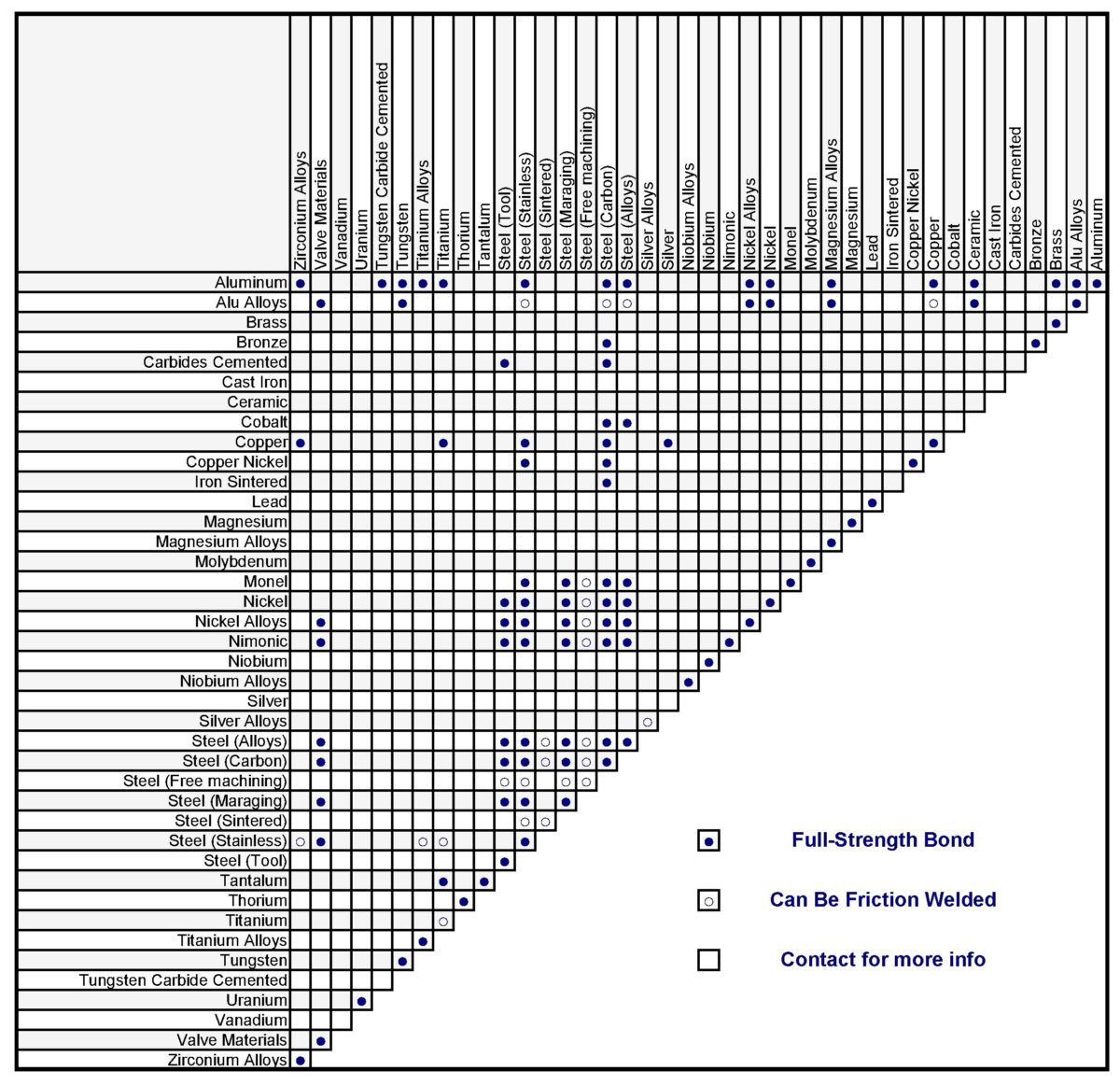
In Rotary friction welding enables to weld various materials. Metallic materials of the same name or dissimilar either composite[1] and non-metallic e.g. thermoplastic polymers[13] can be welded. Weldability tables of metallic alloy can fine on the Internet and books.[11] Sometimes is used interlayer to connect non compatible materials.[10]

Rotary friction welding for plastics
Friction welding is also used to join thermoplastic components.[13]
Division due to drive motor
In direct-drive friction welding (also called continuous drive friction welding) the drive motor and chuck are connected. The drive motor is continually driving the chuck during the heating stages. Usually, a clutch is used to disconnect the drive motor from the chuck, and a brake is then used to stop the chuck.
In inertia friction welding the drive motor is disengaged, and the workpieces are forced together by a friction welding force. The kinetic energy stored in the rotating flywheel is dissipated as heat at the weld interface as the flywheel speed decreases. Before welding, one of the workpieces is attached to the rotary chuck along with a flywheel of a given weight. The piece is then spun up to a high rate of rotation to store the required energy in the flywheel. Once spinning at the proper speed, the motor is removed and the pieces forced together under pressure. The force is kept on the pieces after the spinning stops to allow the weld to "set".[14]
Stages of process

- Step 1 and 2, friction stage: one of the component is set in rotation, and then pressed to the other stationary one in axial of rotation,
- Step 3, braking stage: the rotating component is stopped in braking time,
- Step 4, upsetting stage: the welded elements are still forging by forge pressure (pressed down),
- Step 5: in standard RFW welding (standard parameters), a flash will be created. Flash can be cut off on the welder.[15]

RFW Friction work on cylindrical rods workpieces
Friction work create weld and can believe that is calculated for cylindrical workpieces from math:
Work:
(1)

Moment of force M general formula:
(2)

The force F will be the frictional force T (F=T) so substituting for the formula (2):
(3)

The friction force T will be the pressure F times by the friction coefficient µ:
(4)

So moment of force M:
(5)

The alpha angle that each point will move with the axis of rotating cylindrical workpieces will be:
(6)

So friction work:
(7) [verification needed]

For variable value μ over friction time:
(8)

or variable values μ, n, F over friction time:
(9) [verification needed]

- t [s]- time of friction (when piece rotary),
- μ - coefficient of friction,
- F [N]- pressure force,
- r [m]- radius of workpiece,
- n [1/s] - turnover per second,
- W [J] - friction work.
Therefore, the calculation in this way is not reliable because in reality the process is complicated. The coefficient of friction changes with time, and there are a number of factors internal friction (visiocity - e.g. Dynamic viscosity according to Carreau's fluid law[20]), forge, properties of the material during welding are variable, also there is plastic deformation.
Carreau's fluid law:
Generalized Newtonian fluid where viscosity, , depends upon the shear rate, , by the following equation:


(10)

Where:
- , , and are material coefficients.
- = viscosity at zero shear rate (Pa.s)
- = viscosity at infinite shear rate (Pa.s)
- = relaxation time (s)
- = power index


Modelling of the frictional heat generated within the RFW process can be realized as a function of conducted frictional work and its dissipation coefficient, incremental frictional work of a node 𝑖 on the contacting surface can be described as a function of its axial distance from the rotation centre, current frictional shear stress, rotational speed and incremental time.[21] Where in this paper authors from Hannover University mention that dissipation coefficient 𝛽FR is conventionally set to 0.9 meaning that 90% of frictional work is dissipated into heat.
(11) 𝑑𝑞FR(𝑖) = 𝛽FR ∙ 𝑑𝑊FR(𝑖) = 𝛽FR ∙ 𝜏𝑅(𝑖) ∙ 𝜔 ∙ 𝑟𝑖 ∙ 𝑑𝑡 on contacting surface of node 𝑖[21]
- 𝛽FR - dissipation coefficient,
- 𝑊FR - frictional work,
- 𝑟𝑖 - distance from the rotation centre,
- dt - time increment,
- 𝜏𝑅(𝑖) - current frictional shear stress,
- 𝜔 - rotational speed.
Friction work can also calculate from power of used for welding and friction time (will not be greater than the friction time multiply to the power of the welder - engine of the welder) referring to rules conservation of energy.[verification needed][citation needed]
(12) E = Pxt or for not constant power

- E - energy,
- P - power,
- t - power runtime.
However, in this case, energy can be also stored in the flywheel if is used depending on the welder construction.[verification needed][citation needed]
General flywheel energy formula:
(13)

where:
- is the stored kinetic energy,
- ω is the angular velocity, and
- is the moment of inertia of the flywheel about its axis of symmetry.


Sample calculations not by computer simulation also exist in the literature for example related to power input and temperature distribution can be found in the script from 1974:
K. K. Wang and Wen Lin from Cornell University in "Flywheel friction welding research" manually calculates welding process and even at this time the weld structure was analyzed.[2]
However, generally: The calculations can be complicated.
Heat and mechanical affected zones
Heat and mechanical affected zones
Friction work is converted into rise of temperature in the welding zone area, and as a result of this the weld structure is changed. In typical rotry friction welding process rise of temperature at the beginning of process should be more extensively away from the axis of rotation[11] because points away axis have greater linear velocity and in time of weld the temperature disperses according to thermal conductivity welded parts.
Individual thermomechanical zones can be described by citing an example article:
Anthony R.McAndrew, Paul A.Colegrove, Clement Bühr, Bertrand C.D., Flipo Achilleas Vairis, "A literature review of Ti-6Al-4V linear friction welding", 2018.[22]

"Technically the WCZ and the TMAZ are both "thermo-mechanically affected zones" but due to the vastly different microstructures they possess they are often considered separately. The WCZ experiences significant dynamic recrystallisation (DRX), the TMAZ does not. The material in HAZ is not deformed mechanically but is affected by the heat. The region from one TMAZ/HAZ boundary to the other is often referred to as the "TMAZ thickness" or the plastically affected zone (PAZ). For the remainder of this article this region will be referred to as the PAZ."
Zones:
- WCZ– weld center zone,
- HAZ – heat affected zone,
- TMAZ – Thermo-Mechanically Affected Zone,
- BM – base material, parent material,
- Flash.
Similar terms exist in welding.
During typical welding initially, the outer region heats up more, due to the higher linear velocity.

Next, the heat spreads, and the material is pushed outside, thus creating a flash which can be cut off on the welding machine.

Heat flow, heat flux in rods
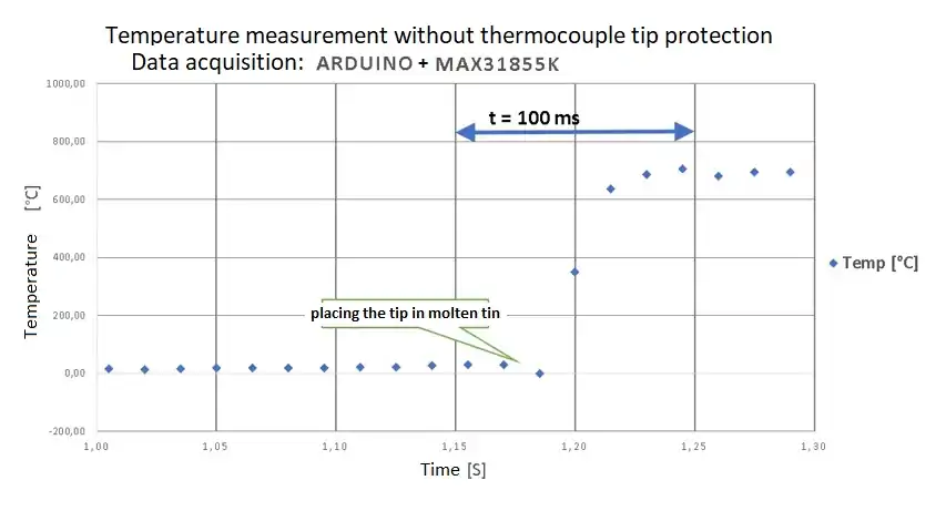
It can create a hypothesis that heat flows in welding time like in a cylindrical rod it makes possible to suppose to calculate a temperature in individual places and times from the knowing of the issues of heat flow and heat flux in rods for example, you can read temperature using thermocouples and compare with computer symulation.


Weld temperature measuring system
Examples of weld measurements. In the literature, can be found measurements of the thermal weld area with e. g. thermocouples[23][24] and not only the non-contact thermographic[24][25] method is also used.

However, it also depends on the specific case for a very small area of the weld and HAZ there are can by difficulties in thermal measuring in real time it can be calculated later after friction time there is heat flow.
Research, temperature, parameters in the rotary friction welding process
Quality requirements of welded joints depend on the form of application, e.g. in the space or fly industry weld errors are not allowed.[26] Science try to gets good quality welds, also some people have been interested for many years in welding knowledge, so there are many scientific articles describing the metods of joining and weld tests, e.g. hardness,[27][28][23] tensile tests.[28] The weld structure can be examined by optical microscopy[28][23][24] and scanning electron microscopy.[29][23][24][28] The computer finite element method (FEM) is used to predict the shape of the flash and interface, not only for rotary friction welding (RFW),[25] but also for friction stir welding (FSW),[30][31] linear friction welding (LFW),[22] FRIEX,[12] and others.

In addition to the weld testing, the weld head affected zones are described.[22] Knowledge of the maximum temperatures in the welding process make it possible to define the area structural changes.[26] Process are analisis e.g. temperature measurements are also carried out for scientific purposes research materials, jurnals, by use contact thermocouples[23][24] or sometimes no contact thermography[25][24] metods. For example, an ultra fine grain structure of alloy or metal which is obtained by techniques such as severe plastic deformation[32][33] is desirable, and not changed by the high temperature, a large heat affected zone is unnecessary. Temperature may reduce material properties because dynamic recrystallization will occur, there maybe changes in grain size and phase transformations[34] structures of welded materials.
Various parameters of welding are tested. The setting of the completely different parameters can obtain different weld for example the structure changes will not be the same width. It is possible to obtain a smaller heat-affected zone (HAZ) and a plastically affected zone (PAZ). The width of the weld is smaller. The results are for example not the same in welds made for the European Space Agency with a high turnover ω = 14000 rpm[29] or another example from Warsaw technical university 12000 rpm[18] and no typical very short friction time only 60 ms[19] instead of using an standard parameters, in addition, in this case, ultra fine grain alloy was welded, but for this example the welded workpiece was only 6mm in diameter[19] another close to this examples with short friction time only e.g 40 ms also exist in literature.[27][1] The rotations in the research literature for small diameters can be more as standard even e.g. 25000 rpm[35][EN citation needed]. Unfortunately the diameter of the workpiece can be a limitation to the use of high speeds of rotation.
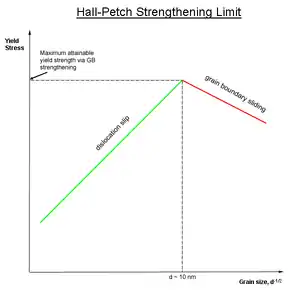
The key points to understand is that: Fine grain of the welded metal material according to Hall-Petch relation should have better strength and for the description of one technique for obtaining this material Percy Williams Bridgman won the Nobel Prize Phisics in 1946[36] referring to the achievements related to High Pressure Torsion (HPT).[37]
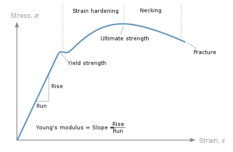 Stress-strain curve typical of a low carbon steel. |
Parameters:
- Turnover: Typically turnover is selected depending on the type of material and dimensions of welded parts have different values: 400 - 1450 rpm, sometimes max 10000 rpm.[11] Not typically, in research literature turnover is to 25000 rmp.[35]
- Friction time: typically 1 - to a few seconds. Not typically, in research literature friction time can be in tends of milliseconds.
- Forge time: Up to a few seconds.
| Table with sample book typical parameters of the welding process.[11] | ||||||
| Materials | Diameter [mm] | Rotation speed [RPM] | Pressure [MPa] | Friction time
[s] |
Burn off rate
[mm] | |
| Friction | Forge | |||||
| steel S235JR + steel S235JR | 40 | 750 | 80 | 100 | 11 | 6-6.5 |
| steel C55 + steel C55 | 40 | 1000 | 100 | 140 | 15 | 11.1 - 11.4 |
| steel 41Cr4 + steel 41Cr4 | 20 | 1000 | 60 | 120 | 8.5 | 5 - 5.5 |
| steel X20Cr13 + steel X20Cr13 | 20 | 1000 | 100 | 206 | 6 | 5.5 |
| steel OOH18M2Nb + steel OOH18M2Nb | 24 | 1450 | 90 | 120 | 225 | - |
| steel X3CrTi17 + steel X3CrTi17 | 35 | 750 | 50 | 100 | 8 | 7 - 7.5 |
| steel X6CrNiTi18 + steel X6CrNiTi18 | 35 | 750 | 90 | 200 | 23 | 6.5 - 7.2 |
| Aluminium + Aluminium | 40 | 750 | 30 | 30 | 9 | 30 |
| copper CW004A + copper CW004A | 35 | 1500 | 52 | 150 | 1 | 8.6 - 9.4 |
| steel 100Cr6 + steel C45 | 22 | 1000 | 50 | 140 | 7 - 8 | 5.6 |
| steel HHS+ C55 | 20 | 1450 | 140 | 160 | 8 | - |
| steel HS18-0-1 + steel C55 | 20 | 1450 | 140 | 160 | 10 | - |
| steel X6CrNiTi18-10 + steel E295 | 40 | 1000 | 110 | 145 | 30 | - |
| Aluminium + steel S235JR | 50 | 400 | 50 | 120 | 7 | 15 |
| copper CW004A + steel S195 | 20 | 1450 | 25 | 160 | 5.3 | 12 |
However, the parameters will be different as elements of different sizes can be welded. For example can be produced ranging from the smallest component with a diameter of 3 mm to large turbine components with a diameter in excess of 400 mm.[5]
Low Force Friction Welding
A improved modification of the standard friction welding is Low Force Friction Welding, hybrid technology developed by EWI and Manufacturing Technology Inc. (MTI),[38][39] "uses an external energy source to raise the interface temperature of the two parts being joined, thereby reducing the process forces required to make a solid-state weld compared to traditional friction welding".[7] The process applies to both linear and rotary friction welding.[7]
Low force friction advantages:[7]
- Little or no flash,
- Joining of components previously limited by friction welding,
- Reduced machine footprint,
- Reduced weld cycle time,
- Higher orientation precision,
- Part repeatability.
Construction of the welding machine

Depending on the construction, but a standard welding machine may include the following systems:
- Control system
- Motor or motors in e.g. direct-drive welder
- Pneumatic or hydraulic pressure system
- Hendle
- Non rotating vise
- Clutch in direct-drive friction welder
- Spindle
- Flywheel in inertia friction welder
- Housing
- Measuring systems
Workpiece handles
The type of chuck depends on the technology used, their construction sometimes may be similar to a lathe and milling machine.
 Three-jaw chuck, multi-jaws are also used. |
 Exemplary handle with a ER Collets (for small diameters of workpiece). |
 Rotary friction welding. |
|---|
Errors during welding
- Components not in the same line of symmetry
- Incomplete welding
- Bad parameters reducing properties of welded components
Safety during welding
- Compliance with occupational safety and health regulations
- Set up the machine in a safe place: not blocking the entrance door, electric wires away from water, free movement of the users
- Covering moving components
Other techniques of friction welding
- Forge welding
- Friction stir welding (FSW) [6][31][23]
- Friction stir spot welding (FSSW)[30]
- Linear friction welding (LFW)[22]
- Friction welding of pipeline girth welds (FRIEX)[12]
- Friction hydro pillar overlap processing (FHPPOW)[40]
- Friction hydro pillar processing (FHHP)[41]
Terms and definitions, name shortcuts
To quote ISO (the International Organization for Standardization) - ISO 15620:2019(en) Welding — Friction welding of metallic materials:
"axial force - force in axial direction between components to be welded,
burn-off length - loss of length during the friction phase,
burn-off rate - rate of shortening of the components during the friction welding process,
component - single item before welding,
component induced braking - reduction in rotational speed resulting from friction between the interfaces,
external braking - braking located externally reducing the rotational speed,
faying surface - surface of one component that is to be in contact with a surface of another component to form a joint,
forge force - force applied normal to the faying surfaces at the time when relative movement between the components is ceasing or has ceased,
forge burn-off length - amount by which the overall length of the components is reduced during the application of the forge force,
forge phase - interval time in the friction welding cycle between the start and finish of application of the forge force,
forge pressure - pressure (force per unit area) on the faying surfaces resulting from the axial forge force,
forge time - time for which the forge force is applied to the components,
friction force - force applied perpendicularly to the faying surfaces during the time that there is relative movement between the components,
friction phase - interval time in the friction welding cycle in which the heat necessary for making a weld is generated by relative motion and the friction forces between the components i.e. from contact of components to the start of deceleration,
friction pressure - pressure (force per unit area) on the faying surfaces resulting from the axial friction force,
friction time - time during which relative movement between the components takes place at rotational speed and under application of the friction forces,
interface - contact area developed between the faying surfaces after completion of the welding operation,
rotational speed - number of revolutions per minute of rotating component,
stick-out - distance a component sticks out from the fixture, or chuck in the direction of the mating component,
deceleration phase - interval in the friction welding cycle in which the relative motion of the components is decelerated to zero,
deceleration time - time required by the moving component to decelerate from friction speed to zero speed,
total length loss (upset) - loss of length that occurs as a result of friction welding, i.e. the sum of the burn-off length and the forge burn-off length,
total weld time - time elapsed between component contact and end of forging phase,
welding cycle - succession of operations carried out by the machine to make a weldment and return to the initial position, excluding component - handling operations,
weldment - two or more components joined by welding."[42]
And more than that:
- RFW - Rotary friction welding,
- LFW - Linear friction welding,
- FSSW - Friction stir spot welding,
- FRIEX - Friction welding of pipeline girth welds,
- FHPPOW - Friction hydro pillar overlap processing,
- FHHP - Friction hydro pillar processing,
- LFFW - Low Force Friction Welding,
- FSW - Friction stir welding,
- BM - Base material,
- HAZ - Heat affected zone,
- PAZ - Plastically affected zone,
- DRX - Dynamic recrystallization,
- TMAZ - Thermo-Mechanically Affected Zone,
- UFG - Ultra fine grain,
- SPD - Serve plastic deformation,
- HPT - High Pressure Torsion,
- FEM - Finite element method,
- SEM - Scanning electron microscopy,
- ADC - Analog to digital converter.
See also
Curiosities
Frictional welding (μFSW) was also performed using a CNC machine.[43] which does not mean that it is safe and recommended for the milling machine.
References
- Siedlec, Robert; Strąk, Cezary (2020-10-10). "Rotary friction welding of Al/Al2O3 Composites with Aluminium Alloys". Welding Technology Review. 92 (6): 23–34. doi:10.26628/wtr.v92i6.1124. ISSN 2449-7959.
- K. K. WANG, WEN LIN (1974). "Flywheel Friction Welding Research" (PDF). Supplement to the Welding Journal.
- J. LOPERA, K. MUCIC, F. FUCHS, N. ENZINGER (October 2012). "Linear Friction Welding Of High Strenght Chains: Modeling And Validation". Mathematical Modelling of Weld Phenomena. 10.
- Mehmet UZKUT, Bekir Sadık ÜNLÜ, Selim Sarper YILMAZ, Mustafa AKDAĞ. "Friction Welding And Its Applications In Today's World" (PDF).
- "Rotary friction welding machines". KUKA AG. Retrieved 2020-12-27.
- Thomas, W.M., Nicholas, E.D., Needham, J.C., Murch, M.G., Templesmith, P., Dawes, C. J., 1991. Improvements to Friction Welding. GB Patent Application No. 91259788.
- Jones, Simon. "Low Force Friction Welding -- What is it?". blog.mtiwelding.com. Retrieved 2020-12-25.
- "Rotary Friction Welding - Job Knowledge". www.twi-global.com. Retrieved 2020-12-27.
- "Rotary friction welding for geothermal applications". www.twi-global.com. Retrieved 2021-01-05.
- "Rotary friction welding for medical application". www.twi-global.com. Retrieved 2021-01-05.
- Klimpel, A. (2009). Spawanie zgrzewanie i cięcie metali (in Polish). Wydawnictwo Naukowo-Techniczne. ISBN 978-83-204-3625-9.
- Pissanti, Daniela Ramminger; Scheid, Adriano; Kanan, Luis Fernando; Dalpiaz, Giovani; Kwietniewski, Carlos Eduardo Fortis (January 2019). "Pipeline girth friction welding of the UNS S32205 duplex stainless steel". Materials & Design. 162: 198–209. doi:10.1016/j.matdes.2018.11.046. ISSN 0264-1275.
- Troughton, Michael J. (2008-10-17). Handbook of Plastics Joining: A Practical Guide. William Andrew. ISBN 9780815519768.
- Rotary Friction Welding, video and schematic diagram
- "Thompson friction welding machines". KUKA AG. Retrieved 2020-12-25.
- "What is Rotary Friction Welding (RFW)?". www.linkedin.com. Retrieved 2020-12-25.
- Stütz, Markus; Buzolin, Ricardo; Pixner, Florian; Poletti, Cecilia; Enzinger, Norbert (May 2019). "Microstructure development of molybdenum during rotary friction welding". Materials Characterization. 151: 506–518. doi:10.1016/j.matchar.2019.03.024. ISSN 1044-5803.
- B. Skowrońska, T. Chmielewski, W. Pachla, M. Kulczyk, J. Skiba, W. Presz (2019). "Friction Weldability of UFG 316L Stainless Steel" (PDF). Arch. Metall. Mater. 3, 64: 1051–1058. doi:10.24425/amm.2019.129494.CS1 maint: multiple names: authors list (link)
- Skowrońska, Beata; Siwek, Piotr; Chmielewski, Tomasz; Golański, Dariusz (2018-05-10). "Zgrzewanie tarciowe ultradrobnoziarnistej stali 316L". Przegląd Spawalnictwa - Welding Technology Review. 90 (5). doi:10.26628/ps.v90i5.917. ISSN 2449-7959.
- "Friction Welding Simulation Software | Software Virtua RFW". sampro (in German). Retrieved 2020-12-27.
- H. Wester, B. A. Behrens, A. Chugreev, C. Kock, K. Brunotte, T. Matthias (2020). "FE-simulation of rotary friction welding process considering thermomechanical-metallurgical coupling" (PDF). Institute of Forming Technology and Machines, Leibniz University of Hannover, Garbsen, 30823, Germany, uni-hannover.de.
- McAndrew, Anthony R.; Colegrove, Paul A.; Bühr, Clement; Flipo, Bertrand C.D.; Vairis, Achilleas (2018-10-03). "A literature review of Ti-6Al-4V linear friction welding". Progress in Materials Science. 92: 225–257. doi:10.1016/j.pmatsci.2017.10.003. ISSN 0079-6425.
- Liu, F. J.; Fu, L.; Chen, H. Y. (2018-02-14). "Effect of high rotational speed on temperature distribution, microstructure evolution, and mechanical properties of friction stir welded 6061-T6 thin plate joints". The International Journal of Advanced Manufacturing Technology. 96 (5–8): 1823–1833. doi:10.1007/s00170-018-1736-0. ISSN 0268-3768.
- Wang, Guilong; Li, Jinglong; Xiong, Jiangtao; Zhou, Wei; Zhang, Fusheng (2018-06-05). "Study on microstructure evolution of AISI 304 stainless steel joined by rotary friction welding". Welding in the World. 62 (6): 1187–1193. doi:10.1007/s40194-018-0613-7. ISSN 0043-2288. S2CID 139498947.
- Nan, Xujing; Xiong, Jiangtao; Jin, Feng; Li, Xun; Liao, Zhongxiang; Zhang, Fusheng; Li, Jinglong (2019). "Modeling of rotary friction welding process based on maximum entropy production principle". Journal of Manufacturing Processes. 37: 21–27. doi:10.1016/j.jmapro.2018.11.016. ISSN 1526-6125.
- J. Pilarczyk A. Piotr. (2013). Poradnik inżyniera 1 – spawalnictwo (in Polish). Warszawa: Wydawnictwo WNT.
- Siedlec, Robert; Strąk, Cezary; Zybała, Rafał (2016-11-10). "Morfologia złączy kompozytów Al/Al2O3 zgrzewanych tarciowo ze stopem Al 44200". Przegląd Spawalnictwa - Welding Technology Review (in Polish). 88 (11). doi:10.26628/ps.v88i11.706. ISSN 2449-7959.
- Shanjeevi, C.; Satish Kumar, S.; Sathiya, P. (2013). "Evaluation of Mechanical and Metallurgical Properties of Dissimilar Materials by Friction Welding". Procedia Engineering. 64: 1514–1523. doi:10.1016/j.proeng.2013.09.233. ISSN 1877-7058.
- M. Meisnar, S. Baker, J.M. Bennett, A. Bernad, A. Mostafa, S. Resch, N. Fernandes, A. Norman (2017). "Microstructural characterization of rotary friction welded AA6082 and Ti-6Al-4V dissimilar joints". Materials & Design. 132: 188–197. doi:10.1016/j.matdes.2017.07.004.CS1 maint: multiple names: authors list (link)
- Lacki, P.; Kucharczyk, Z.; Śliwa, R.E.; Gałaczyński, T. (2013-06-01). "Effect of Tool Shape on Temperature Field in Friction Stir Spot Welding". Archives of Metallurgy and Materials. 58 (2): 595–599. doi:10.2478/amm-2013-0043. ISSN 1733-3490.
- Qin, D. Q.; Fu, L.; Shen, Z. K. (2019-01-15). "Visualisation and numerical simulation of material flow behaviour during high-speed FSW process of 2024 aluminium alloy thin plate". The International Journal of Advanced Manufacturing Technology. 102 (5–8): 1901–1912. doi:10.1007/s00170-018-03241-5. ISSN 0268-3768.
- Rosochowski, Andrzej (2013). Severe plastic deformation technology. Place of publication not identified: Whittles Publishing. ISBN 978-1-84995-119-7. OCLC 968912427.
- Gianluca Buffa, Łukasz Morawiński, Livan Fratini, Małgorzata Lewandowska, Marta Orłowska, Lech Olejnik, Davide Campanella (2020-08-01). "Application of linear friction welding for joining ultrafine grained aluminium". Journal of Manufacturing Processes. 56: 540–549. doi:10.1016/j.jmapro.2020.05.012. ISSN 1526-6125.CS1 maint: multiple names: authors list (link)
- Cui, Ling; Fujii, Hidetoshi; Tsuji, Nobuhiro; Nakata, Kazuhiro; Nogi, Kiyoshi; Ikeda, Rinsei; Matsushita, Muneo (2007). "Transformation in Stir Zone of Friction Stir Welded Carbon Steels with Different Carbon Contents". ISIJ International. 47 (2): 299–306. doi:10.2355/isijinternational.47.299. ISSN 0915-1559.
- Pietras, Bogucki, Adam, Bogucki (2005). "Charakterystyka zgrzewania tarciowego elementów konstrukcji metalowych" (PDF). Szybkobieżne Pojazdy Gąsienicowe (21) nr 1, 2005 (in Polish).
- "List of Nobel laureates in Physics", Wikipedia, 2020-11-30, retrieved 2020-12-21
- ZHILYAEV, A; LANGDON, T (August 2008). "Using high-pressure torsion for metal processing: Fundamentals and applications". Progress in Materials Science. 53 (6): 893–979. doi:10.1016/j.pmatsci.2008.03.002. ISSN 0079-6425.
- "Joining Bimetallics with Low Force Friction Welding". Buffalo Manufacturing Works. 2020-11-30. Retrieved 2020-12-25.
- Gould, Jerry (2020). "Application of Low Force Friction Welding to a 6061-T6 Aluminum Alloy". Retrieved 2021-01-15.
- Buzzatti, Diogo Trento; Chludzinki, Mariane; Santos, Rafael Eugenio dos; Buzzatti, Jonas Trento; Lemos, Guilherme Vieira Braga; Mattei, Fabiano; Marinho, Ricardo Reppold; Paes, Marcelo Torres Piza; Reguly, Afonso (2019). "Toughness properties of a friction hydro pillar processed offshore mooring chain steel". Journal of Materials Research and Technology. 8 (3): 2625–2637. doi:10.1016/j.jmrt.2019.04.002. ISSN 2238-7854.
- Buzzatti, Diogo Trento; Buzzatti, Jonas Trento; Santos, Rafael Eugenio dos; Mattei, Fabiano; Chludzinski, Mariane; Strohaecker, Telmo Roberto (2015). "Friction Hydro Pillar Processing: Characteristics and Applications". Soldagem & Inspeção. 20 (3): 287–299. doi:10.1590/0104-9224/si2003.04. ISSN 0104-9224.
- "iso:15620". www.iso.org. Retrieved 2021-02-05.
- Wang, Kaifeng; Khan, Haris Ali; Li, Zhiyi; Lyu, Sinuo; Li, Jingjing (October 2018). "Micro friction stir welding of multilayer aluminum alloy sheets". Journal of Materials Processing Technology. 260: 137–145. doi:10.1016/j.jmatprotec.2018.05.029. ISSN 0924-0136.
External links
- Rotary Friction Welding at google scholar
- Rotary Friction Welding at TWI and search-results at TWI
- Rotary Friction Welding at KUKA
