Cable layer
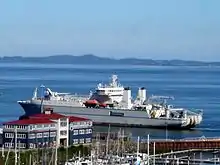
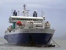
A cable layer or cable ship is a deep-sea vessel designed and used to lay underwater cables for telecommunications, electric power transmission, military, or other purposes. Cable ships are distinguished by large cable sheaves[1] for guiding cable over bow or stern or both. Bow sheaves,[2] some very large, were characteristic of all cable ships in the past, but newer ships are tending toward having stern sheaves only, as seen in the photo of CS Cable Innovator at the Port of Astoria on this page. The names of cable ships are often preceded by "C.S." as in CS Long Lines.[3]


The first transatlantic telegraph cable was laid by cable layers in 1857–58. It briefly enabled telecommunication between Europe and North America before misuse resulted in failure of the line. In 1866 the SS Great Eastern successfully laid two transatlantic cables, securing future communication between the continents.
Modern cable ships
Cable ships have unique requirements related to having long idle periods in port between cable laying or repairs, operation at low speeds or stopped at sea during cable operations, long periods running astern (less frequent as stern layers are now common), high maneuverability, and a fair speed to reach operation areas.[4]
Modern cable ships differ greatly from their predecessors. There are two main types of cable ships: cable repair ships and cable-laying ships. Cable repair ships, like the Japanese Tsugaru Maru, tend to be smaller and more maneuverable; they are capable of laying cable, but their primary job is fixing or repairing broken sections of cable. A cable-laying ship, like Long Lines, is designed to lay new cables. Such ships are bigger than repair ships and less maneuverable; their cable storage drums are also larger and are set in parallel so one drum can feed into another, allowing them to lay cable much faster. These ships are also generally equipped with a linear cable engine (LCE) that helps them lay cable quickly. By locating the manufacturing plant near a harbor, cable can be loaded into the ship's hold as it is being manufactured.[5]
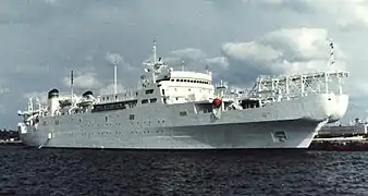
The newest design of cable layers, though, is a combination of cable-laying and repair ships. An example is USNS Zeus (T-ARC-7) the only U.S. naval cable layer-repair ship. Zeus uses two diesel-electric engines that produce 5000 horsepower each and can carry her up to 15 knots (about 17 miles per hour), and she can lay about 1000 miles (≈1600 kilometers) of telecommunications cable to a depth of 9000 feet (≈2700 meters). The purpose of Zeus was to be a cable ship that could do anything required of it, so the ship was built to be able to lay and retrieve cable from either the bow or the stern with ease. This design was similar to that of the first cable ship, Great Eastern. Zeus was built to be as maneuverable as possible so that it could fulfill both roles: as a cable layer or a cable repair ship.[6]
Equipment
To ensure that cable is laid and retrieved properly, specially designed equipment must be used. Different equipment is used on cable-laying ships depending on what their job requires. In order to retrieve damaged or mislaid cable, a grapple system is used to gather cable from the ocean floor. There are several types of grapples, each with certain advantages or disadvantages. These grapples are attached to the vessel via a grapple rope, originally a mix of steel and manila lines, but now made from synthetic materials. This ensures that the line is strong, yet can flex and strain under the weight of the grapple. The line is pulled up by reversing the Linear Cable Engine used to lay the cable.[7]

The most common laying engine in use is the Linear Cable Engine (LCE). The LCE is used to feed the cable down to the ocean floor, but this device can also be reversed and used to bring back up cable needing repair. These engines can feed 800 feet of cable a minute. However, ships are limited to a speed of 8 knots while laying cable to ensure the cable lies on the sea floor properly and to compensate for any small adjustments in course that might affect the cables' position, which must be carefully mapped so that they can be found again if they need to be repaired. Linear Cable Engines are also equipped with a brake system that allows the flow of cable to be controlled or stopped if a problem arises. A common system used is a fleeting drum, a mechanical drum fitted with eoduldes (raised surfaces on the drum face) that help slow and guide the cable into the LCE.[7] Cable ships also use “plows” that are suspended under the vessel. These plows use jets of high-pressure water to bury cable 3 feet under the sea floor, which prevents fishing vessels from snagging cables as thrall their nets.[8]
HMTS Monarch[9] (renamed CS Sentinel 13 October 1970)[1] completed the first transatlantic telephone cable, TAT-1, in 1956[10] from Scotland to Nova Scotia for Britain's General Post Office (GPO).
Repeaters
When coaxial cables were introduced as submarine cables, a new issue with cable-laying was encountered. These cables had periodic repeaters inline with the cable and powered through it. Repeaters overcame significant transmission problems on submarine cables. The difficulty with laying repeaters is that there is a bulge where they are spliced in to the cable and this causes problems passing through the sheave. British ships, such as HMTS Monarch and HMTS Alert solved the problem by providing a trough for the repeater to bypass the sheave. A rope connected in parallel to the repeater went through the sheave which pulled the cable back in to the sheave after the repeater had passed. It was normally necessary for the ship to slow down while the repeater was being laid.[11] American ships, for a time, tried using flexible repeaters which passed through the sheave. However, by the 1960s they were also using rigid repeaters similar to the British system.[12]
Another issue with coaxial repeaters is that they are much heavier than the cable. To ensure that they sink at the same rate as the cable (which can take some time to reach the bottom) and keep the cable straight, the repeaters are fitted with parachutes.[12][11]:212
List of cable ships

- Goliath, the first ship to lay an ocean cable in 1850. Done for the Submarine Telegraph Company across the English Channel.
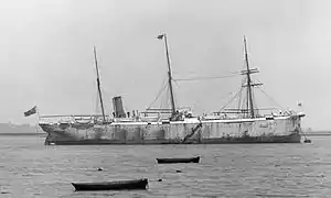
- CS Monarch (1830), first ship to be permanently fitted out as a cable ship
- SS Great Eastern, worked as a cable ship from 1865 to 1870
- CS Hooper, launched 29 March 1873 for Hooper's Telegraph Works, first cable ship designed to lay trans Atlantic cable, renamed CS Silvertown in 1881[13][14]
- CS H. C. Oersted, named for Hans Christian Ørsted built for The Great Northern Telegraph Company 1872, was the first ship specifically designed for cable repair.[15]
- CS Seine, maiden voyage 1873[16][17]
- CS Faraday, built in 1874 for Siemens Brothers
- CS Gomos, the first cable ship ever to be sunk; she was rammed by another ship in the 1870s while laying a cable for the Brazilian Submarine Telegraph Company.[18][19][20]:137
- CS La Plata, chartered by Siemens Brothers Ltd. from W.T. Henley’s Telegraph Works Co. to lay cable between Rio de Janeiro, Brazil and Chuy, Uruguay to complete work after CS Gomos sunk. Foundered 29 November 1874 in the Bay of Biscay with loss of 58 crew and the cable.[19][21]
- CS Mackay-Bennett, in service from 1884 until 1922, and best known for recovering the bodies of the victims of the RMS Titanic disaster in 1912
- CS Alert (1890), cut important German cables in World War I
- CS Cambria (1905), sank in Montevideo harbour, Uruguay, in 1945
- CS Faraday (1923)
- CS Telconia, in service from 1910 until 1934
- CS Monarch (1945)
Royal Navy
- HMS Pique (1834), fifth-rate frigate used in 1845 as a cable ship
- HMS Agamemnon (1852), 91-gun steam line-of-battle ship used as a cable ship in 1857 as part of the effort to lay the first transatlantic telegraph cable
- HMS Thrush (1889), composite gunboat used briefly as a cable ship in 1915
- HMS Squirrel (1904), coast guard vessel used as a cable ship in 1917
US Navy

- USS Portunus (ARC-1) 1951-1959
- USNS Neptune (ARC-2) 1973-1992
- USS Aeolus (ARC-3) 1973-1985
- USS Thor (ARC-4) 3 January 1956 to 2 July 1973 [22]
- USS Yamacraw (ARC-5) 1959-1965
- USNS Albert J. Myer (T-ARC-6) 1963-1994
- USNS Zeus (T-ARC-7) 1984–present, only ship in class
See also
References
- "History of the Atlantic Cable & Submarine Telegraphy - HMTS Monarch (4)". atlantic-cable.com. Retrieved 24 March 2019.
- "NavSource Photo, USS Neptune (ARC 2) bow sheaves". navsource.org. Retrieved 24 March 2019.
- "History of the Atlantic Cable & Submarine Telegraphy - Leo Parrish and CS Long Lines". atlantic-cable.com. Retrieved 24 March 2019.
- Gill, A. J. (January 1947). "H.M.T.S. Monarch" (PDF). The Post Office Electrical Engineers' Journal. London: The Institution of Post Office Electrical Engineers. 39 (January 1947): 129–138. Retrieved 29 January 2020.
- How the Internet Travels Across Oceans, by Adam Satariano, graphics By Karl Russell, Troy Griggs and Blacki Migliozzi, photographs by Chang W. Lee, New York Times, March 10, 2019
- Sanderlin, T., Stuart, W., & Jamieson, D.R., (1979). Cable Laying Ship. Presented at the April 18, 1979, meeting of Chesapeake Section of The Society of Naval Architects and marine Engineers.
- Thomas N. Sanderlin, Stuart M. Williams & Robert D. Jamison.(1979).Cable Laying Ship.Presented at the April 18, 1979, meeting of Chesapeake Section of The Society of Naval Architects and marine Engineers.
- Frank, D. Messia; Jon, B. Machin; Jeffery, A.Hill. (2000). The Economic Advantages of Jet-Assisted Plowing.Source: Oceans Conference Record (IEEE), v 1, p 649-656, 2001; ISSN 0197-7385; DOI: 10.1109/OCEANS.2001.968800; Conference: Oceans 2001 MTS/IEEE - An Ocean Odyssey, November 5, 2001 - November 8, 2001; Sponsor: Marine Technology Society; IEEE; OES; Publisher: Institute of Electrical and Electronics Engineers Inc.
- "hmts-alert.org.uk - Registered at Namecheap.com". www.hmts-alert.org.uk. Archived from the original on 18 January 2017. Retrieved 24 March 2019.
- "History of the Atlantic Cable & Submarine Telegraphy - Cable Signalling Speed". atlantic-cable.com. Retrieved 24 March 2019.
- K. R. Haigh, Cableships and Submarine Cables, pp. 211–214, Adlard Coles, 1968 OCLC 497380538.
- "Two new British cable ships completed", New Scientist, No. 240, p. 716, 22 June 1961.
- Glover, Bill (22 December 2019). "History of the Atlantic Cable & Submarine Telegraphy - CS Hooper/Silvertown". Retrieved 22 January 2020.
- "Launch of a Telegraph Steamer". The London and China Telegraph. Lonfon. 15 (501): 229. April 7, 1873. Retrieved 22 January 2020.
- Glover, Bill (4 March 2017). "History of the Atlantic Cable & Submarine Telegraphy - CS H. C. Oersted". Retrieved 27 January 2020.
- Glover, Bill. "The Evolution of Cable & Wireless, Part 3". Atlantic-cable.com. Retrieved 21 February 2019.
- "Ship Seine". The Illustrated London News. 1 November 1873. Retrieved 21 February 2019.
The ship Seine laying the land end of the Brazilian submarine telegraph cable at Madeira, illustration from the magazine The Illustrated London News, volume LXIII, November 1, 1873.
- Glover, Bill. "History of the Atlantic Cable & Submarine Telegraphy - CS Gomos". Retrieved 25 January 2020.
- "Telegraphic Progress in 1874". Engineering. London. 19 (January 1875): 12–13. 1874.
- Huurdeman, Anton A., The Worldwide History of Telecommunications, Wiley, 2003 ISBN 0471205052.
- Glover, Bill. "History of the Atlantic Cable & Submarine Telegraphy - CS La Plata". Retrieved 25 January 2020.
- "Attack Cargo Ship AKA-49 Vanadis". www.navsource.org. Retrieved 24 March 2019.
External links
| Wikimedia Commons has media related to Cable-laying ships. |
- International Cable Protection Committee - Cableships of the World
- Photos of commercial cable layers
- C.S. Long Lines
- History of the Atlantic Cable & Undersea Communications
- The World's Submarine Telephone Systems (Extensive glossary, review of systems with discussion of ship equipment)
- South American Cables 1891-1892 Example of detailed description of cable and cable laying late 19th century.
- "Laying the New Ocean Cable" (Popular Science Dec. 1928, CS Dominia)
- "Cable Laying Ship Is Floating Wonderland" (Popular Mechanics July 1932)
- United States Army Signal Corps Scrapbook Related to U.S. cable ship Burnside at Dartmouth College Library
.jpeg.webp)
