Counterpoise (ground system)
In electronics and radio communication a counterpoise is a network of suspended horizontal wires or cables (or a metal screen), used as a substitute for an earth (ground) connection in a radio antenna system. It is used with radio transmitters or receivers when a normal earth ground cannot be used because of high soil resistance[1] or when an antenna is mounted above ground level, for example, on a building. It usually consists of a single wire or network of horizontal wires, parallel to the ground, suspended above the ground under the antenna, connected to the receiver or transmitter's "ground" wire.[2] The counterpoise functions as one plate of a large capacitor, with the conductive layers of the earth acting as the other plate.[2][3]
The counterpoise evolved with the Marconi (monopole) antenna during the 1890s, the first decade of radio in the wireless telegraphy era, but it was particularly advocated by British radio pioneer Oliver Lodge,[4][5] and patented by his associate Alexander Muirhead[6] in 1907.[7]
How it works
Counterpoises are typically used in antenna systems for radio transmitters where a good earth ground connection cannot be constructed.
Monopole antennas used at low frequencies, such as the mast radiator antennas used for AM broadcasting, require the radio transmitter to be electrically connected to the Earth under the antenna; this is called a ground (or earth). The ground must have a low electrical resistance, because any resistance in the ground connection will dissipate power from the transmitter. Low-resistance grounds for radio transmitters are normally constructed of a network of cables buried in the earth. However, in areas with dry, sandy or rocky soil the ground has a high resistance, so a low-resistance ground connection cannot be made. In these cases, a counterpoise is used. Another circumstance in which a counterpoise is used is when earth for a buried ground under the antenna mast is not available, such as in antennas located in a city or on top of a tall building.
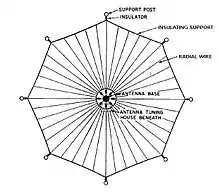
A common design for a counterpoise is a series of radial wires suspended a few feet above the ground, extending from the base of the antenna in all directions in a "star" pattern, connected at the centre.[2] The counterpoise functions as one plate of a large capacitor, with the conductive layers in the earth as the other plate.[2] Since the radio frequency alternating currents from the transmitter can pass through a capacitor, the counterpoise functions as a low-resistance ground connection. There should not be any closed loops in the wires of a counterpoise system, as the strong fields of the antenna will induce circular currents in it which will dissipate transmitter power.
Use at low frequencies
The largest use of counterpoises is in transmitters on the low frequency (LF) and very low frequency (VLF) bands, as they are very sensitive to ground resistance.[2] Because of the large wavelength of the radio waves, feasible antennas used at these frequencies are electrically short, their length is a small fraction of the wavelength. The radiation resistance of antennas (the resistance that represents power radiated as radio waves) drops as their length becomes small compared to a wavelength, so the radiation resistance of antennas on the LF and VLF bands is very low, often as low as one ohm or less. The other, larger resistances in the antenna-ground circuit can consume significant portions of the transmitter’s power. The largest resistance in the antenna-ground circuit is often the ground system, and the transmitter power is divided proportionally between it and the radiation resistance, so the resistance of the ground system has to be kept very low to minimize the "wasted" transmitter power.
However, at low frequencies the resistance of even a good ground system in high conductivity soil can consume a major portion of the transmitter power. Another source of resistance is dielectric losses from the penetration of radio waves into the ground near the antenna due to the large skin depth at low frequencies. Therefore, particularly at VLF frequencies, large counterpoises are often used instead of buried grounds, to reduce the ground system resistance, allowing more of the transmitter power to be radiated.
Sometimes a counterpoise is combined with an ordinary ground, with the buried radial ground cables brought above ground near the base of the antenna to form a counterpoise. The area of the counterpoise around the base of the antenna is often covered with copper screening, to shield the ground to reduce ground currents.
Size
The size of the counterpoise used for radio work depends on the wavelength of the transmit frequency. With a monopole antenna, the counterpoise functions as a ground plane, reflecting the radio waves radiated downward by the antenna. To perform adequately, the counterpoise should extend at least half a wavelength from the antenna tower in all directions.[8] In designing a counterpoise for a medium-wave radio station, for example, radio-waves are a maximum of 566 metres (1,857 ft) long. Therefore, the counterpoise should extend 282 metres (925 ft) from the tower to make a circle 566 metres (1,857 ft) in diameter.
See also
References
- Cebik, L. B. (December 31, 2009). "Counterpoise? On the Use and Abuse of a Word". antenneX. Archived from the original on December 19, 2016. Retrieved 25 September 2010. Alt URL
- Laporte, Edmund (1952). Radio Antenna Engineering. MicGraw-Hill. pp. 52–53.
- United States Bureau of Naval Personnel (1973). Basic Electronics. Washington DC: Courier Corp. p. 523. ISBN 9780486210766.
- Lodge, Oliver (1925). Talks about Wireless. Cambridge University Press. pp. 91–92. ISBN 110805269X.
- Simmons, Harold H. (1908). Outlines of Electrical Engineering. New York: Cassell and Co. pp. 853–854.
- Alexander Muirhead, British patent no. 11271 "Hertzian Wireless Telegraphy"
- Eckersley, T. L. (May 1922). "An investigation of transmitting aerial resistances". Proc. Of the Inst. Of Electrical Engineers. London: E. and F. N. Spon. 60 (309): 599. Retrieved October 3, 2013.
- 20th edition of The ARRL Antenna Book in 2003, page 2-16