Monopole antenna
A monopole antenna is a class of radio antenna consisting of a straight rod-shaped conductor, often mounted perpendicularly over some type of conductive surface, called a ground plane.[1][2][3] The driving signal from the transmitter is applied, or for receiving antennas the output signal to the receiver is taken, between the lower end of the monopole and the ground plane. One side of the antenna feedline is attached to the lower end of the monopole, and the other side is attached to the ground plane, which is often the Earth. This contrasts with a dipole antenna which consists of two identical rod conductors, with the signal from the transmitter applied between the two halves of the antenna.
The monopole is often used as a resonant antenna; the rod functions as an open resonator for radio waves, oscillating with standing waves of voltage and current along its length. Therefore the length of the antenna is determined by the wavelength of the radio waves it is used with. The most common form is the quarter-wave monopole, in which the antenna is approximately one quarter of the wavelength of the radio waves. However in broadcasting monopole antennas 5/8 = 0.625 wavelength long are also popular, because at this length a monopole radiates a maximum amount of its power in horizontal directions. The monopole antenna was invented in 1895 by radio pioneer Guglielmo Marconi; for this reason it is sometimes called the Marconi antenna.[4][5][6] Common types of monopole antenna are the whip, rubber ducky, helical, random wire, umbrella, inverted-L and T-antenna, inverted-F, mast radiator, and ground plane antennas.
The load impedance of the quarter-wave monopole is half that of the dipole antenna or 37.5+j21.25 ohms.
History
The monopole antenna was invented in 1895 and patented in 1896[7] by radio pioneer Guglielmo Marconi during his historic first experiments in radio communication. He began by using dipole antennas invented by Heinrich Hertz consisting of two identical horizontal wires ending in metal plates. He found by experiment that if instead of the dipole, one side of the transmitter and receiver was connected to a wire suspended overhead, and the other side was connected to the Earth, he could transmit for longer distances. For this reason the monopole is also called a Marconi antenna,[4][5][6] although Alexander Popov independently invented it at about the same time.[8][9][10][11]
Radiation pattern
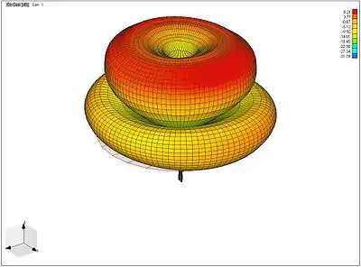
Like a dipole antenna, a monopole has an omnidirectional radiation pattern: it radiates with equal power in all azimuthal directions perpendicular to the antenna. However, the radiated power varies with elevation angle, with the radiation dropping off to zero at the zenith of the antenna axis. It radiates vertically polarized radio waves.

A monopole can be visualized (right) as being formed by replacing the bottom half of a vertical dipole antenna (c) with a conducting plane (ground plane) at right-angles to the remaining half. If the ground plane is large enough, the radio waves from the remaining upper half of the dipole (a) reflected from the ground plane will seem to come from an image antenna (b) forming the missing half of the dipole, which adds to the direct radiation to form a dipole radiation pattern. So the pattern of a monopole with a perfectly conducting, infinite ground plane is identical to the top half of a dipole pattern, with its maximum radiation in the horizontal direction, perpendicular to the antenna. Because it radiates only into the space above the ground plane, or half the space of a dipole antenna, a monopole antenna will have a gain of twice (3 dB greater than) the gain of a similar dipole antenna, and a radiation resistance half that of a dipole. Since a half-wave dipole has a gain of 2.19 dBi and a radiation resistance of 73 ohms, a quarter-wave monopole, the most common type, will have a gain of 2.19 + 3 = 5.19 dBi and a radiation resistance of about 36.8 ohms if it is mounted above a good ground plane.[12]
The general effect of electrically small ground planes, as well as imperfectly conducting earth grounds, is to tilt the direction of maximum radiation up to higher elevation angles.[13]
Types
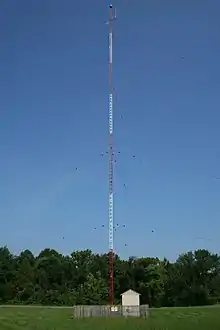
For monopole antennas operating at lower frequencies, below 20 MHz, the ground plane is usually the Earth; in this case the antenna is mounted on the ground and one side of the feedline is connected to an earth ground at the base of the antenna. In transmitting antennas to reduce ground resistance this is often a radial network of buried wires stretching outward from the antenna. This design is used for the mast radiator transmitting antennas employed for radio broadcasting in the MF and LF bands. At lower frequencies the antenna mast is electrically short giving it a very small radiation resistance, so to increase efficiency and radiated power capacitively toploaded monopoles such as the T-antenna and umbrella antenna are used.
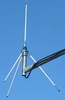
At VHF and UHF frequencies the size of the ground plane needed is smaller, so artificial ground planes are used to allow the antenna to be mounted above the ground. A common type of monopole antenna at these frequencies consists of a quarter-wave whip antenna with a ground plane consisting of several wires or rods radiating horizontally or diagonally from its base; this is called a ground-plane antenna. At gigahertz frequencies the metal surface of a car roof or airplane body makes a good ground plane, so car cell phone antennas consist of short whips mounted on the roof, and aircraft communication antennas frequently consist of a short conductor in an aerodynamic fairing projecting from the fuselage; this is called a blade antenna.[12]
The quarter-wave whip and rubber ducky antennas used with handheld radios such as walkie-talkies and portable FM radios are also monopole antennas. The antenna used in cell phones is the inverted-F antenna, which is a variant of the inverted-L monopole. Bending over the antenna saves space and keeps the it within the bounds of the mobile's case but the antenna then has a very low impedance. To improve the match the antenna is not fed from the end, rather some intermediate point, and the end is grounded instead. In these portable devices the antenna does not have an effective ground plane, the ground side of the transmitter is just connected to the ground connection on its circuit board. Since the circuit board ground is often smaller than the antenna, the antenna/ground combination may function more as an asymmetrical dipole antenna than a monopole. The hand and body of the person holding them may function as a rudimentary ground plane.
Sometimes, monopole antennas are printed on a dielectric substrate to make it less fragile and they may be fabricated easily using the printed circuit board technologies. Such antennas are known as printed monopole antennas. They are suitable for various applications such as RFID and wireless networking.[14]
See also
- Dual-band blade antenna
- Cellular repeater
- Signal strength
- Folded unipole antenna
- Electrical lengthening
References
- Poisel, Richard (2012). Antenna Systems and Electronic Warfare Applications. Artech House. p. 223. ISBN 9781608074846.
- Bevelacqua, Peter J. (2016). "The Monopole Antenna". Antenna Types. Antenna-Theory.com website. Retrieved 20 August 2020.
- Straw, R. Dean, Ed. (2000). The ARRL Antenna Book, 19th Ed. American Radio Relay League. p. 2.17. ISBN 9780872598041.
- Das, Sisir K. (2016). Antenna and Wave Propagation. Tata McGraw-Hill Education. p. 116. ISBN 978-1259006326.
- Wong, K. Daniel (2011). Fundamentals of Wireless Communication Engineering Technologies. John Wiley and Sons. p. 94. ISBN 978-1118121092.
- Kishore, Kamal (2009). Antenna and Wave Propagation. IK International Ltd. p. 93. ISBN 978-9380026060.
- US patent 586193, Guglielmo Marconi Transmitting electrical signals, filed December 7, 1896, granted July 13, 1897
- Visser, Hubregt J. (2006). Array and Phased Array Antenna Basics. John Wiley and Sons. p. 31. ISBN 0470871180.
- Howeth, L. S. (1963). The History of Communications - Electronics in the U.S. Navy. U.S. Navy. pp. 19.
- Meinel, Christoph; Sack, Harald (2014). Digital Communication: Communication, Multimedia, Security. Springer Science and Business Media. p. 55. ISBN 978-3642543319.
- Stutzman, Warren L.; Thiele, Gary A. (2012). Antenna Theory and Design. John Wiley and Sons. p. 8. ISBN 978-0470576649.
- Macnamara, Thereza (2010). Introduction to Antenna Placement and Installation. USA: John Wiley and Sons. p. 145. ISBN 978-0-470-01981-8.
- Weiner, Melvin M. Weiner (2003). Monopole antennas. USA: CRC Press. pp. vi. ISBN 0-8247-4844-1.
- J. R. Panda, A. S. R. Saladi, Rakhesh Singh Kshetrimayum, "A Compact Printed Monopole Antenna for Dualband RFID and WLAN Applications, " Radioengineering, vol. 20, no. 2, June 2011, pp. 464-467